2.30JIFFY STAND
CLEANING
The jiffy stand locks when placed in the full forward (down)
position with vehicle weight on it. If the jiffy stand is not
in the full forward (down) position with vehicle weight on
it, the vehicle can fall over which could result in death or
serious injury. (00006a)
Always park motorcycle on a level, firm surface. An
unbalanced motorcycle can fall over, which could result
in death or serious injury. (00039a)
Be sure jiffy stand is fully retracted before riding. If jiffy
stand is not fully retracted, it can contact the road surface
causing a loss of vehicle control, which could result in
death or serious injury. (00007a)
1. Block motorcycle underneath frame so both wheels are
raised off the ground.
2. See Figure 2-114. Inspect top of catch (6). If covered with
dirt, wipe dirt off with a shop towel and spray catch and
mating surface with LOCTITE AEROSOL ANTI-SEIZE.
3. Move jiffy stand leg (3) forward and back to infuse anti-
seize into mating parts.
4. If catch is covered with mud/grime, remove bolt (7) and
catch (6).
5. Clean catch (6) and pivot block mating surface (5).
6. Spray LOCTITE AEROSOL ANTI-SEIZE on shaft of jiffy
stand leg and pin (2) to lubricate the mating surface
between pin and pivot block (5). Move leg back and forth
and downward while spraying lubricant.
7. Assemble the catch so it engages the flats on the shaft of
the jiffy stand leg and secure with bolt (7).
8. Tighten bolt (7) to 19 ft-lbs (25.8 Nm).
9. Check that jiffy stand operates correctly before using.
SENSOR (HDI MODELS)
1. See Figure 2-114. Make a note of harness routing for ease
of assembly. Disconnect sensor connector located under
the seat.
2. Remove cable anchors (2).
3. Remove screw (4) and remove sensor (3).
4. If necessary, remove screw (1) and remove sensor bracket
(5).
5. Installation is in reverse of removal.Tighten screws (1, 4)
to 96-144 in-lbs (10.8-16.3 Nm).
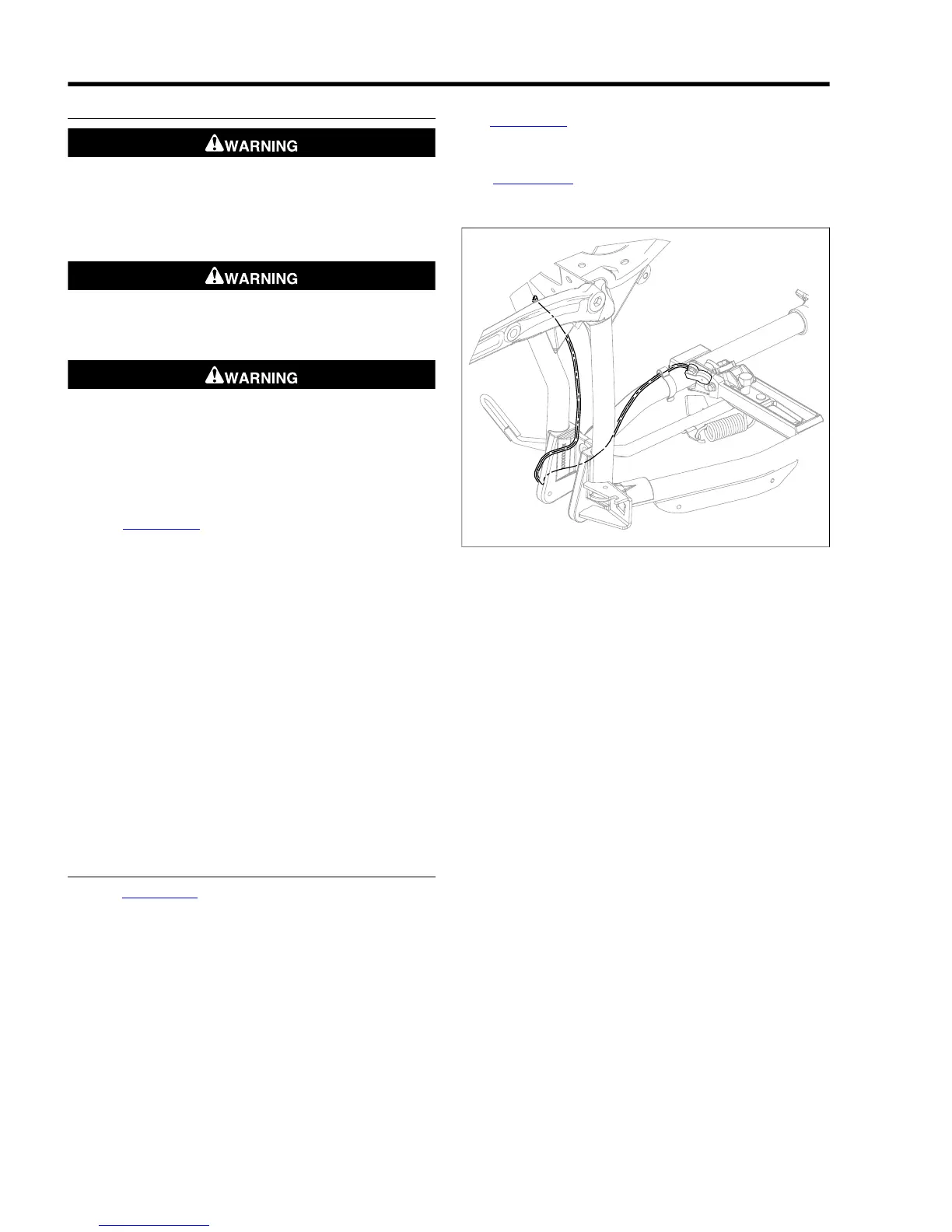
NOTE
See Figure 2-112. Ensure the sensor harness is routed to the
inside of the left-lower frame and under the rear engine mount
casting.
See Figure 2-113. Route the sensor harness in the same
retainer cavity (3) as the vent tube (2).