until loose. Remove the rocker arm support plate bolts
with flat washers.
6. Remove the rocker arm support plate assembly from the
rocker housing. For inspection and repair information, see
3.20 ROCKER ARM SUPPORT PLATE.
NOTE
Always service each cylinder separately. After the first cylinder
is serviced the engine must be rotated to find the base circle
on the second cam. Service on the remaining cylinder can then
proceed.
Figure 3-21. Crankshaft Rotating Wrench
PUSH RODS, LIFTERS AND COVERS
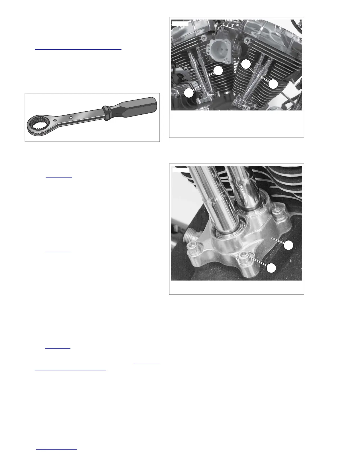
1. See Figure 3-22. Remove the intake and exhaust push
rods and push rod covers.
a. Tag the push rods for location (front/rear cylinder),
and orientation (top/bottom) as they are removed.
This will simplify installation.
b. Remove push rod covers from cylinder head and lifter
cover bores.
c. Remove three o-rings from push rod covers and dis-
card. If o-ring is missing from upper push rod cover,
be sure to dislodge it from the cylinder head bore.
2. See Figure 3-23. Remove lifter covers.
a. Using a crosswise pattern, remove four screws with
captive washers (1) to release the lifter cover (2).
b. Remove the lifter cover and gasket. Discard gasket.
3. Remove lifters.
a. Remove the anti-rotational pin to free the hydraulic
lifters.
b. Tag the lifters for location (front/rear cylinder) and
function (intake/exhaust) as they are removed. This
will simplify installation.
c. Place the lifters in clean plastic bags to keep out dust,
dirt and debris.
4. See Figure 3-24. Remove and discard o-ring from groove
around breather baffle hole in rocker housing.
5. For inspection and repair information, see 3.21 PUSH
RODS, LIFTERS AND COVERS.
1. Front cylinder exhaust push rod
2. Front cylinder intake push rod
3. Rear cylinder intake push rod
4. Rear cylinder exhaust push rod
Figure 3-22. Push Rod Locations