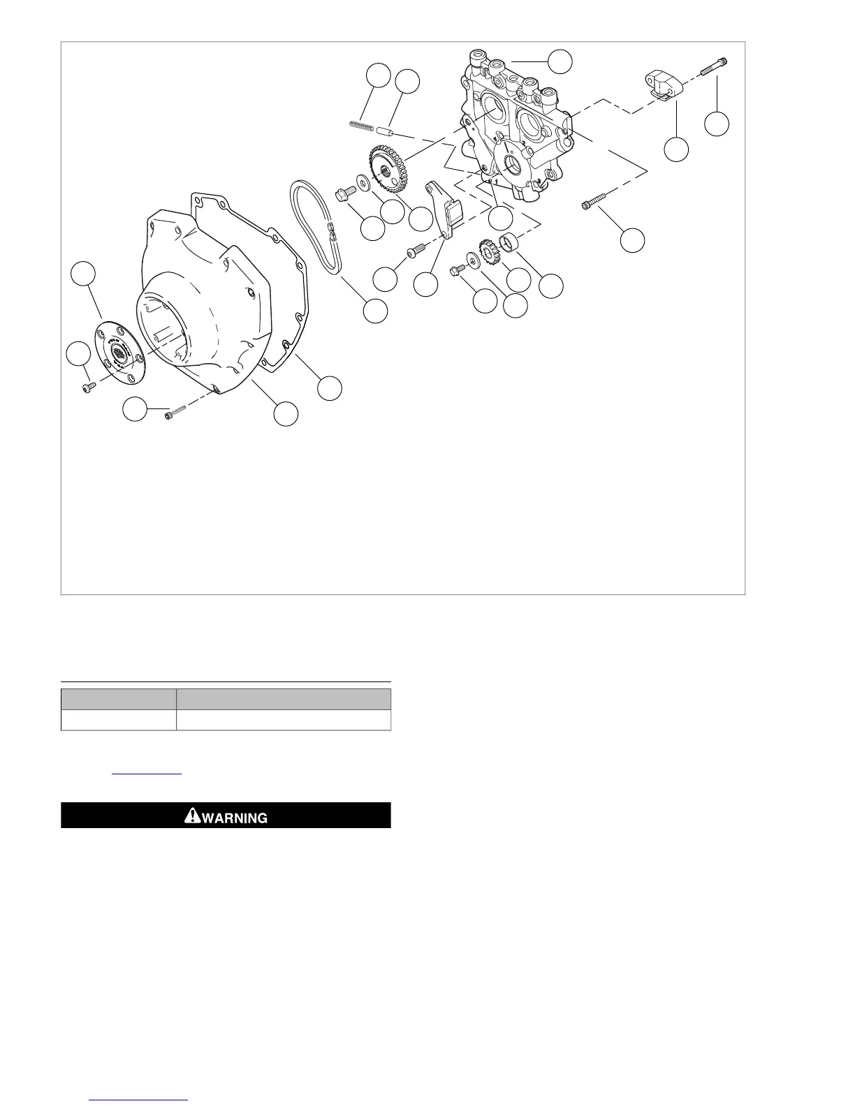
12.1. Flange bolt, smallIgnition cover fastener
2. 13.Ignition cover Flat washer
14.3. Crank sprocketCam cover fastener
4. 15.Cam cover Crankshaft bushing
16.5. Roll pinCam cover gasket
6. 17.Primary cam chain Cam support plate fastener (8)
18.7. FastenerFlange bolt, large
8. 19.Flat washer Secondary cam chain tensioner
20.9. Cam support plateRear cam sprocket
10. 21.Fastener Oil pressure relief valve
22.11. Valve springPrimary cam chain tensioner
Figure 3-113. Cover and Cam Support Plate Assembly
CAMSHAFTS
TOOL NAMEPART NUMBER
CAMSHAFT ASSEMBLY TOOLHD-47956
Removal
1. See Figure 3-114. Remove screws (4) and remove sec-
ondary cam chain tensioner (3).
Wear safety glasses or goggles when removing or
installing retaining rings. Retaining rings can slip from the
pliers and could be propelled with enough force to cause
serious eye injury. (00312a)
2. Remove retaining ring from groove at end of front cam-
shaft. Discard retaining ring.
3. Do not mix front and rear camshaft spacers. Front spacer
is 0.100 in. (2.54 mm) thick.
4. Using a colored marker, mark one of the links of the sec-
ondary cam chain. Maintaining the original direction of
rotation during assembly may prolong service life.
5. Slide camshafts and secondary cam chain out of cam
support plate.
6. Remove secondary cam chain from cam sprockets.
3-82 2008 Dyna Service: Engine



 To Next Page