3.26OIL PUMP
REMOVAL OVERVIEW
1. See 3.15 TOP END OVERHAUL: DISASSEMBLY.
a. Remove breather assembly.
b. Remove rocker arm support plate.
c. Remove push rods and push rod covers. Do not
remove lifters or lifter covers.
2. Fashion lifter holding tool to prevent the hydraulic lifters
from dropping into the cam compartment during cam
support plate removal. See 3.25 COVER AND CAM
SUPPORT PLATE.
3. To remove cover and cam support plate, see
3.17 BOTTOM END OVERHAUL: DISASSEMBLY.
Remove oil pump after removing cam support plate.
CLEANING AND INSPECTION
1. Clean all parts in a non-volatile cleaning solution or
solvent.
Compressed air can pierce the skin and flying debris from
compressed air could cause serious eye injury. Wear
safety glasses when working with compressed air. Never
use your hand to check for air leaks or to determine air
flow rates. (00061a)
2. Blow parts dry with low pressure compressed air. Verify
that all oil passages are clean and open.
3. Look for scoring, gouging or cracking caused by foreign
material that may have passed through the oil pump.
4. Look for grooves or scratches on the cam support plate,
which serves as the outboard side of the oil pump.
5. Check for excessive wear or damage on lobes of outer
gerotor gears and between lobes on inner gerotor gears.
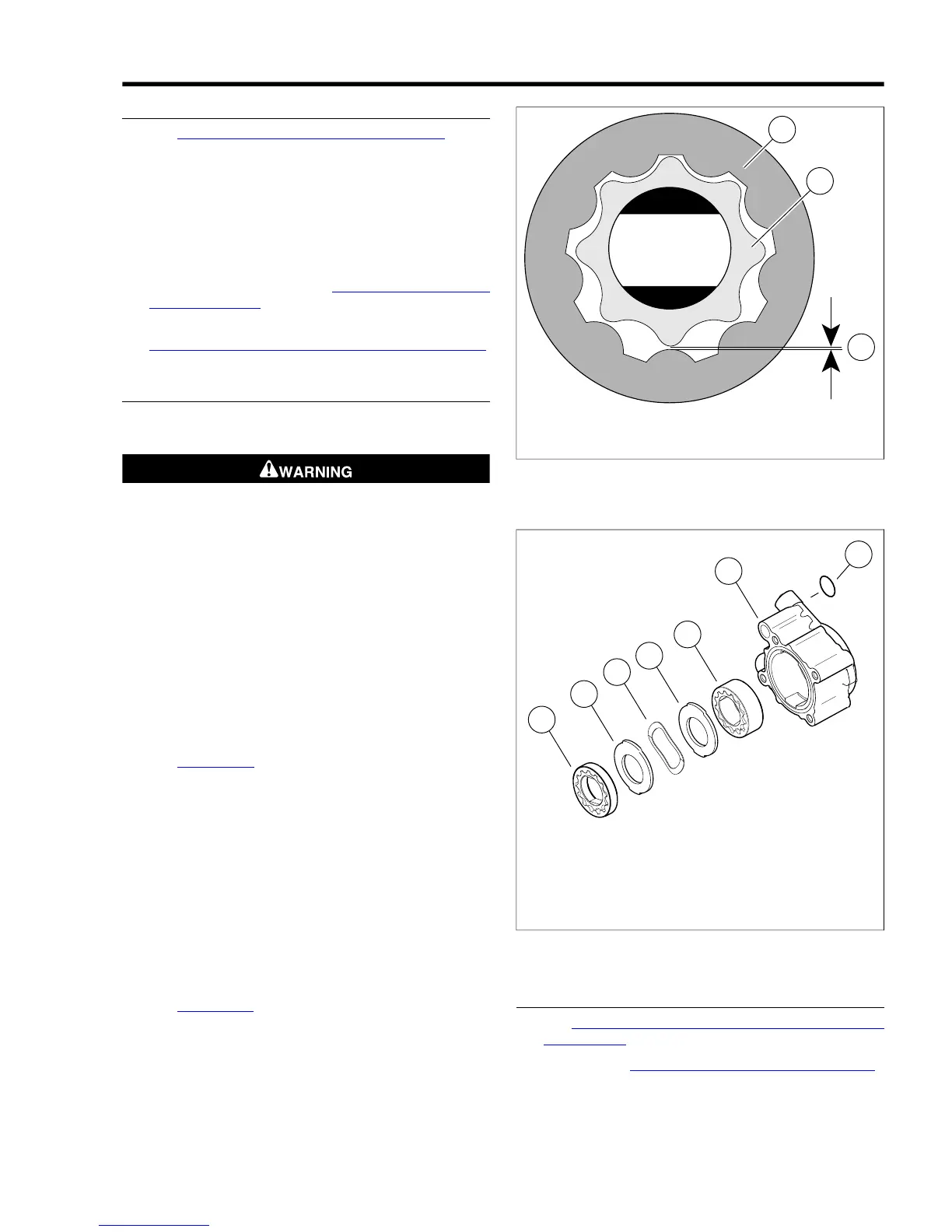
6. See Figure 3-128. Check gerotor wear.
a. Mesh pieces of one gerotor set together.
b. Use a feeler gauge to determine clearance between
tips of lobes on inner and outer gerotors.
c. Replace gerotors as a set if clearance exceeds 0.004
in. (0.10 mm). Inspect second gerotor set in the same
manner.
7. Measure thickness of inner gerotor of one set with a
micrometer. Measure the outer gerotor of the same set.
Replace the gerotor set if the difference exceeds 0.001
in. (0.025 mm). Inspect second gerotor set in the same
manner.
8. See Figure 3-129. Assemble the oil pump.Verify that feed
gerotors stand proud of the oil pump surface 0.015-0.025
in. (0.381-0.635 mm). If measurement is less than 0.015
in. (0.381 mm), remove feed gerotor set and reassemble
using new wave washer. Repeat measurement and
replace oil pump body if still not within specification.



 To Next Page