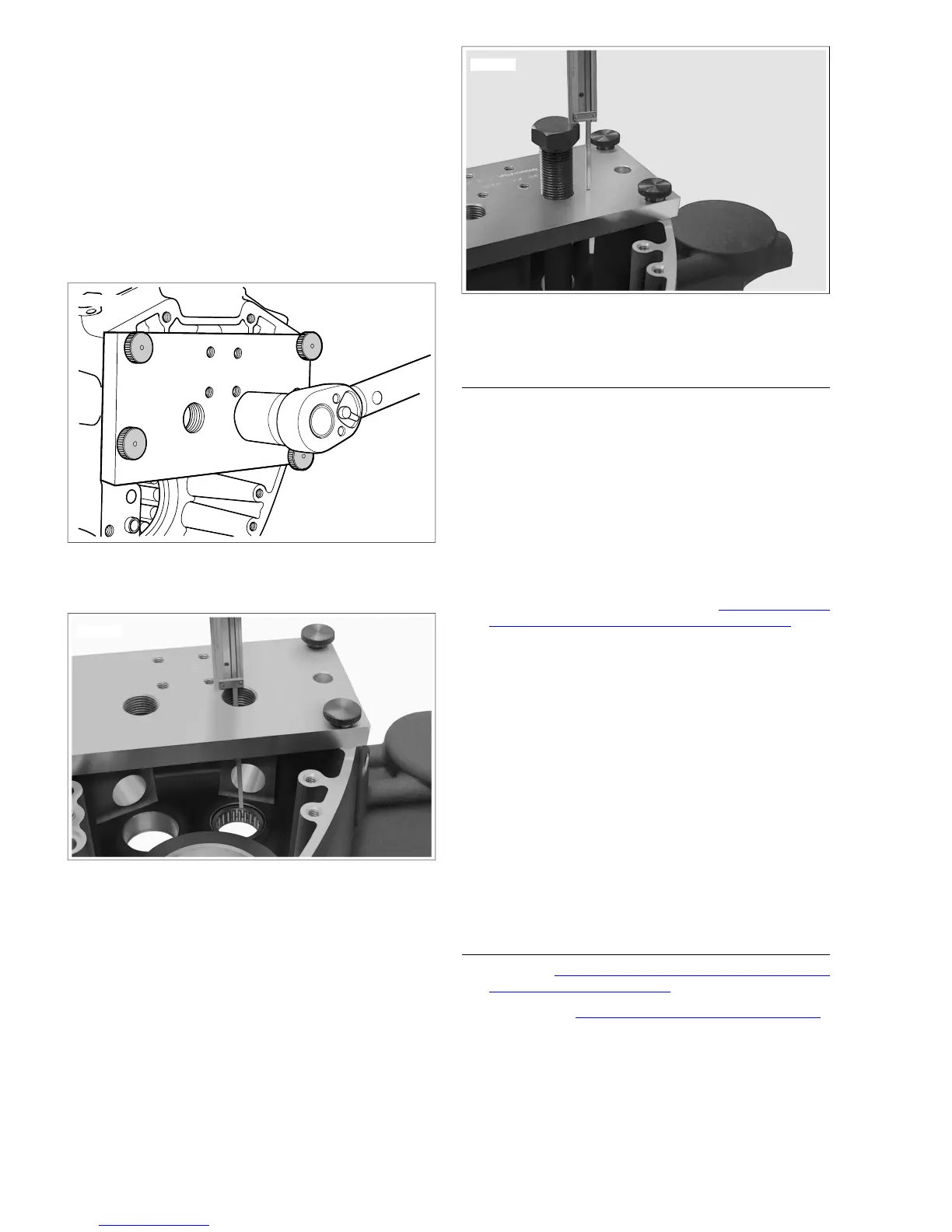
12. Install forcing screw in support plate over second needle
bearing bore. Reaching into crankcase, place installer at
end of forcing screw. Place new needle bearing on installer
with lettered side facing shoulder.
NOTE
In next step, do not exceed 25 ft-lbs (33.9 Nm) to install
bearing. If this specification is exceeded, bearing could push
through case causing damage to case and bearing.
13. Using torque wrench, turn hex on forcing screw in a
clockwise direction until distance from head (top) of forcing
screw to support plate equals measurement obtained
previously.
Figure 3-127. Measure from Top of Forcing Screw to
Support Plate
CLEANING AND INSPECTION
Oil Pressure Valve
NOTE
If diagnosing low oil pressure, start with step 1. If diagnosing
high oil pressure, then begin with step 2.
1. Insert straight stiff wire into unplugged hole outboard of
roll pin until it bottoms. Mark wire and measure distance
from edge of cam support plate to inboard side of piston.
With piston fully seated in the bore, depth should be
approximately 2.25 in. (57.15 mm). If it is not, continue
with next step.
2. Remove oil pressure relief valve. See 3.25 COVER AND
CAM SUPPORT PLATE, Oil Pressure Relief Valve.
3. Inspect spring for stretching, kinking or distortion.
4. Inspect piston and bore for burrs, scoring or other damage.
Look for steel particles or aluminum chips. Replace cam
support plate and piston if any of these conditions are
found.
5. Install piston in bore and measure running clearance. If
running clearance exceeds 0.003 in. (0.076 mm), install
new piston and remeasure. Replace cam support plate if
running clearance still exceeds specification.
Cam Support Plate
Verify that all oil holes are clean and open.
NOTE
Exercise caution to avoid enlarging the oil holes or oil pressure
will be adversely affected.
INSTALLATION OVERVIEW
1. Begin with 3.18 BOTTOM END OVERHAUL: ASSEMBLY,
Cover and Cam Support Plate.
2. Continue with 3.16 TOP END OVERHAUL: ASSEMBLY.
3-88 2008 Dyna Service: Engine



 To Next Page