2. Since measuring from the top of the support plate is easier
and produces the most accurate and consistent results,
proceed as follows:
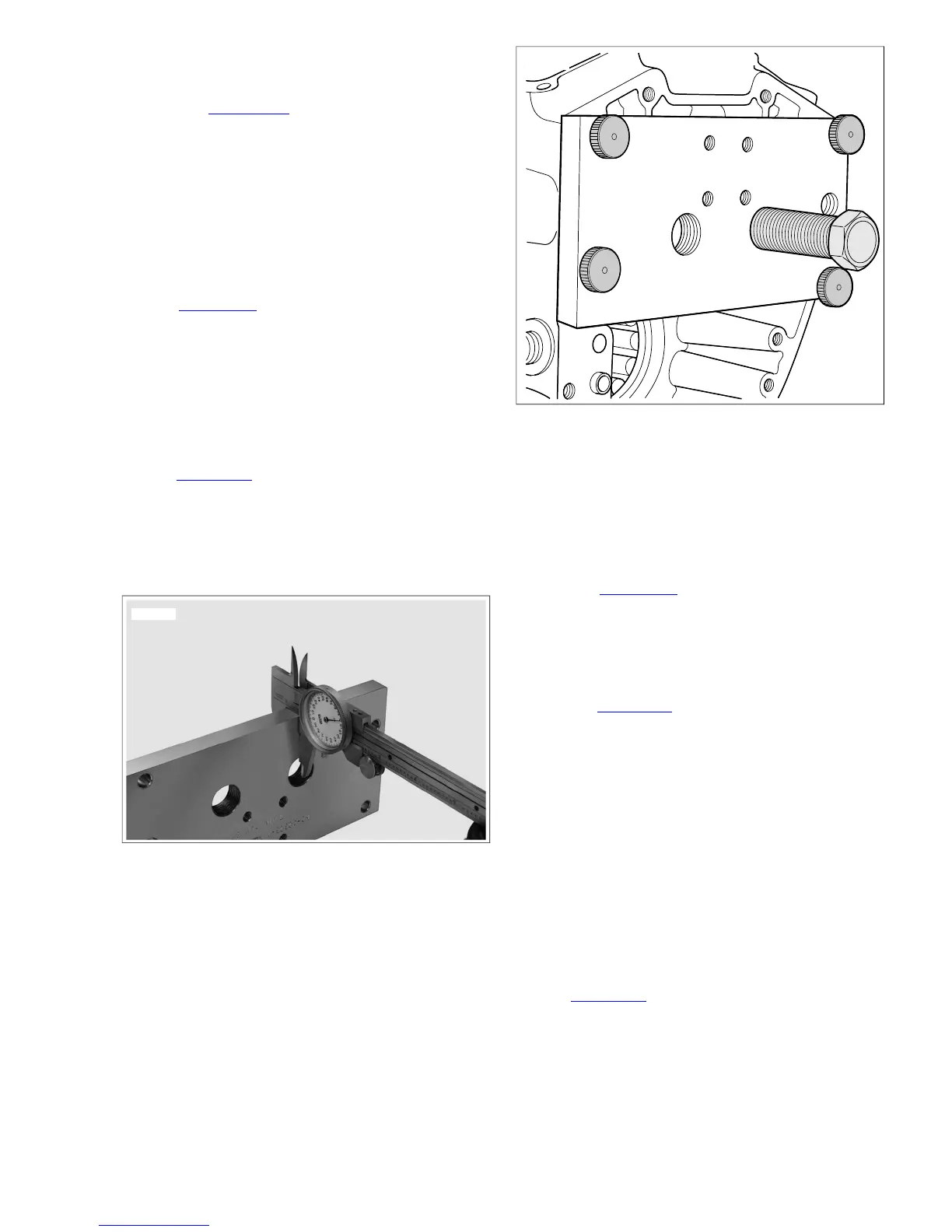
a. See Figure 3-123. Using a dial caliper, measure
thickness of support plate.
b. To determine the required distance from the top of
the support plate to the edge of the installed needle
bearing, add measurement obtained in the previous
step to 3.10 in. (78.7 mm).
NOTE
For example, if the support plate is 0.50 in. (12.7 mm) thick,
then the measurement from the top of the support plate to the
edge of the needle bearing should be 3.60 in. (91.4 mm).
3. See Figure 3-121. Sparingly apply graphite lubricant (9)
to threads of installer forcing screw (4) to prolong service
life and ensure smooth operation.
4. Thread installer forcing screw into stamped side of support
plate (2) until threads begin to emerge from opposite side.
5. Place installer (6) at end of installer forcing screw.
6. Place new needle bearing on installer with lettered side
facing shoulder.
7. See Figure 3-124. Aligning two large holes in support plate
with needle bearing bores, hang right side of plate on ring
dowel in crankcase flange.
8. Align four holes at corners of support plate with threaded
holes in crankcase flange. Install thumb screws in these
holes to secure support plate to crankcase.
Figure 3-124. Installer Forcing Screw Installation
9. Install first needle bearing as follows:
a. Obtain torque wrench and set to 25 ft-lbs (33.9 Nm).
NOTE
In next step, do not exceed 25 ft-lbs (33.9 Nm) to install
bearing. If this specification is exceeded, bearing could
push through case causing damage to case and bearing.
b. See Figure 3-125. Using torque wrench, turn hex at
end of installer forcing screw in a clockwise direction
to press needle bearing into bore
c. Back out forcing screw. Reaching into crankcase,
remove installer. Remove forcing screw from support
plate.
d. See Figure 3-126. Inserting dial caliper through forcing
screw bore, measure distance from top of support
plate to edge of needle bearing.
e. Install forcing screw in support plate. Reaching into
crankcase, place installer at end of forcing screw.
Hand turn forcing screw until shoulder on installer
makes contact with edge of needle bearing.
f. Repeat the previous steps until needle bearing is
installed to the correct depth (as calculated previ-
ously).
NOTE
In the next step, a measurement will be taken of the distance
from the head of the installer forcing screw to the support plate.
For an accurate measurement, be sure the shoulder on the
installer is in contact with the edge of the needle bearing.
10. See Figure 3-127. Using a dial caliper, measure from head
(top) of installer forcing screw to support plate. Record
this measurement for use in installing second needle
bearing.
11. Back out forcing screw. Reaching into crankcase, remove
installer. Remove forcing screw from support plate.
2008 Dyna Service: Engine 3-87



 To Next Page