2. Position ends of head pipe assembly (14) into front and
rear cylinder head exhaust ports with holes in exhaust
manifold flanges (11) over cylinder head exhaust studs.
Loosely install flange nuts (12).
3. Slide muffler clamps (21) onto exhaust pipes.
NOTE
TORCA muffler clamps have eliminated the need for silicone
or graphite tape during assembly. To ensure sealing integrity
of muffler clamps, and prevent the possibility of leakage,
Harley-Davidson recommends that the muffler clamp assem-
blies be discarded and replaced each time they are removed.
4. Install front and rear mufflers (22, 23) on exhaust pipes.
Install muffler clamps (21). Do not tighten nuts at this time.
5. Install muffler-to-muffler bolt (1) and washer (2). Do not
tighten at this time.
6. Install muffler mounting bolt (4) and washer (3). Do not
tighten at this time.
NOTE
Align exhaust system and tighten all nuts and bolts, beginning
at cylinder head exhaust ports and working backwards.
7. Tighten flange nuts (12), at front cylinder studs as follows:
a. Install lower nut and tighten finger tight.
b. Install upper nut and tighten to 9-18 in-lbs (1-2 Nm).
c. Tighten lower nut to 100-120 in-lbs (11.3-13.6 Nm).
d. Tighten upper nut to 100-120 in-lbs (11.3-13.6 Nm).
8. Tighten flange nuts at rear cylinder studs as follows:
a. Install upper nut and tighten finger tight.
b. Install lower nut and tighten to 9-18 in-lbs (1-2 Nm).
c. Tighten upper nut to 100-120 in-lbs (11.3-13.6 Nm).
d. Tighten lower nut to 100-120 in-lbs (11.3-13.6 Nm).
9. Open the worm drive clamps (15, 19) and install heat
shields (16, 17, 18).
10. Tighten muffler mounting bolt (43) to 15-19 ft-lbs (20.3-
25.8 Nm).Tighten muffler attaching bolt (1) securely.
11. Align mufflers. Tighten muffler clamp nuts to 45-50 ft-
lbs (61.0-67.8 Nm).
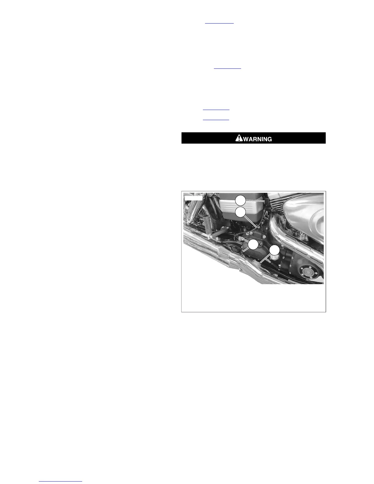
12. See Figure 4-67. On models with an active exhaust
module, install active exhaust cable (1):
a. Install ferrule (3) in bellcrank (4).
b. Wrap cable around bellcrank.
c. Install cable and retainer (2) on exhaust pipe.
d. See Figure 4-69. Ensure cable routing is correct and
secure with two camps (3).
NOTE
Connector halves must be clean and dry. Do not apply dielectric
grease to sealed connectors or terminals.
13. See Figure 4-65. Connect rear O2 sensor connector [137].
14. See Figure 4-61. Connect front O2 sensor connector [138].
Close front electrical caddy cover.
After installing seat, pull upward on seat to be sure it is
locked in position. While riding, a loose seat can shift
causing loss of control, which could result in death or
serious injury. (00070b)
15. Install seat.