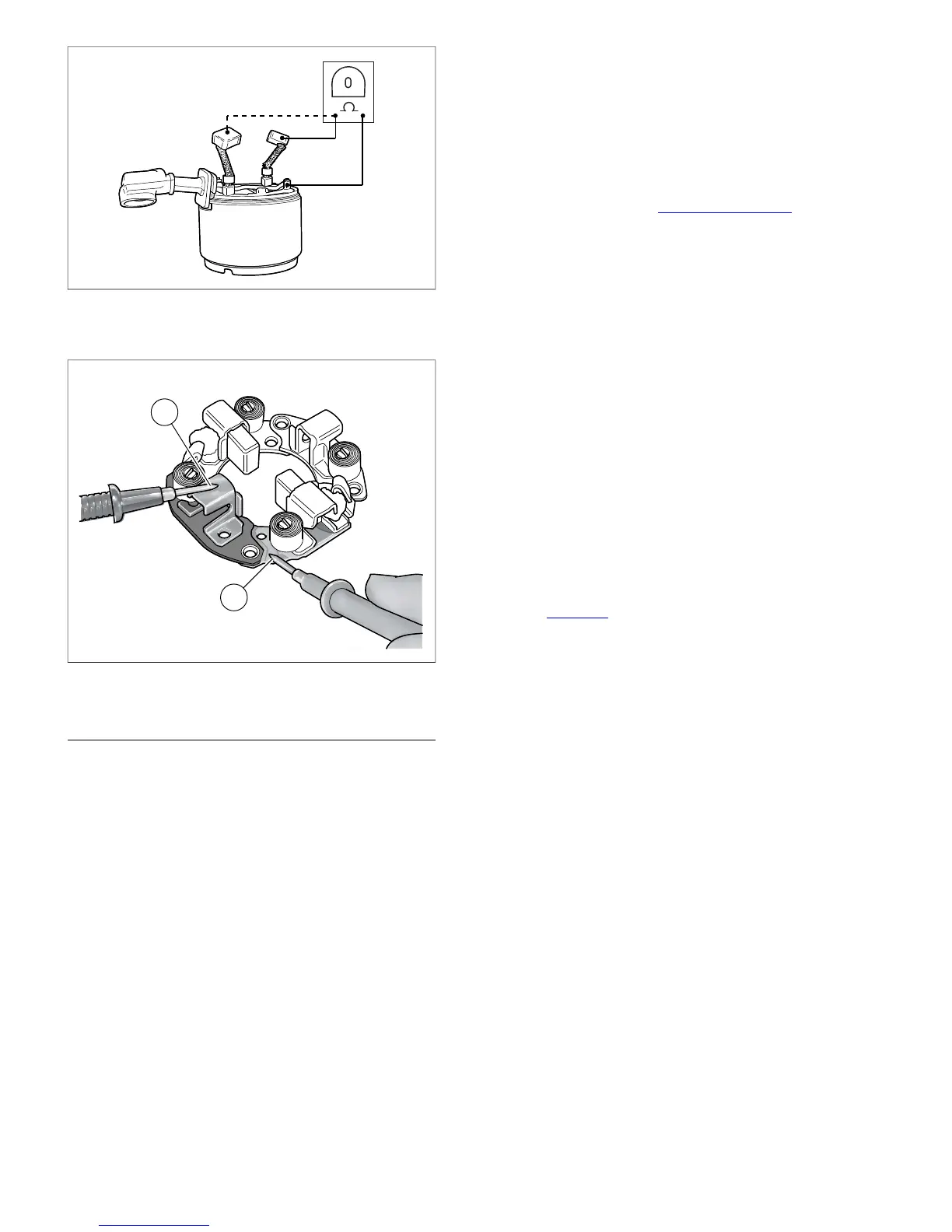
Figure 5-8. Brush Holder Insulation Test
FIELD COIL ASSEMBLY
Disassembly
1. Remove allen head screw to release chrome end cover,
if equipped.
2. Remove two Keps nuts to release end cover bracket from
thru bolts, if equipped.
3. Pull up rubber boot and remove hex nut with captive
lockwasher to release field wire ring terminal from post on
solenoid housing.
4. Using a 5/16 inch socket, loosen two thru bolts to release
field coil from solenoid housing.
5. Pull field coil with end cap from solenoid housing.
6. Remove armature from field coil. Separating end cap and
field coil flanges will facilitate removal.
7. Placing field coil on wooden block to prevent damage, use
impact driver to remove two Phillips screws with captive
washers from end cap. Discard screws.
8. Remove end cap from field coil.
9. Locate the two brushes attached to the field coil winding.
Pushing on inboard side of one brush, grasp free end of
brush spring on outboard side with the hooked end of a
suitable pick. Raise end of brush spring only as far as
necessary to free brush from brush holder. Repeat step
to release second brush and then remove brush holder
from field coil.
Inspection
1. For testing procedures, see 5.2 STARTER, Testing.
2. Inspect two o-rings in field coil bore for cuts, tears or signs
of deterioration.
3. Inspect armature roller bearings. Bearings must rotate
freely without drag or sticking. Replace the bearings if
pitted or grooved.
4. Replace brush springs if bent or distorted.
Assembly
1. Attach brush holder to field coil. Locate the two brushes
attached to the field coil winding. Catch free end of brush
spring with the hooked end of a suitable pick. Raise end
of brush spring only as far as necessary to install brush
into brush holder. Repeat step to install second brush.
2. Retract all four brushes for armature installation. For good
results, obtain four paper clips. Bend free end of each
paper clip outward approximately 90°. Then, pushing on
inboard side of brush, insert straight end of paper clip
between outboard side of brush and inboard side of brush
spring. Properly installed, the paper clip contacts the
framework of the brush holder to keep spring pressure off
the brush. Repeat step on remaining three brushes as
shown in Figure 5-9.
3. Install armature in solenoid housing so that larger bearing
on splined end seats in counterbore. Lubricate armature
bearings with high temperature grease, such as LUBRI-
PLATE 110, before installation.
4. Mate field coil and solenoid housings. For proper
assembly, a nub on the field coil housing flange must
engage the slot on solenoid housing flange closest to the
short (field wire) post on the solenoid housing.
5. Carefully place brush holder over armature. If additional
clearance is needed, use a small flat blade screwdriver to
gently push back the brushes slightly.
6. When the brush holder is centered over the armature,
remove four paper clips to release brush springs. Verify
that ends of brush springs make proper contact with brush
sides.
7. Install end cap aligning holes in cap with those in brush
holder. Start two new Phillips screws with captive washers.
Alternately tighten Phillips screws until snug.
8. Install thru bolts to fasten field coil to solenoid housing.
Using a 5/16 inch socket, alternately tighten thru bolts to
39-65 in-lbs (4.4-7.3 Nm).
9. Attach field wire ring terminal to short post on solenoid
housing and install hex nut with captive lockwasher.
Tighten hex nut to 70-90 in-lbs (7.9-10.2 Nm). Cover field
wire ring terminal with rubber boot.
5-6 2008 Dyna Service: Starter


 To Next Page
 Loading...
