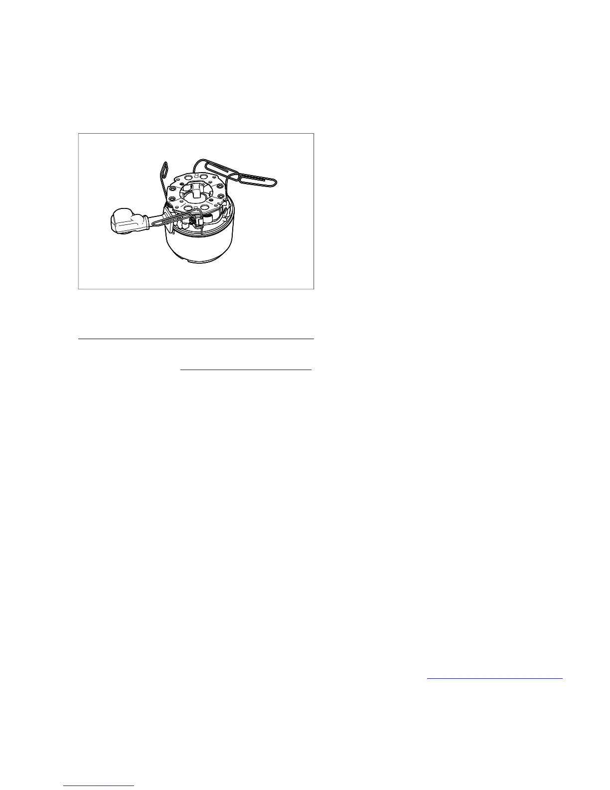
Figure 5-9. Install Paper Clips to Hold Brush Springs
DRIVE ASSEMBLY
Disassembly
1. Remove field coil. See 5.2 STARTER, Field Coil Assembly.
2. Pull field coil with end cap from solenoid housing. Hold
end cap to field coil to avoid pulling armature out of brush
holder. If armature is pulled from brush holder, further
disassembly is required.
3. Using a 9 mm socket, remove two hex screws with Phillips
recess to release drive housing from solenoid housing.
4. Use a rubber mallet to separate drive and solenoid hous-
ings, if necessary.
5. Remove idler gear from bearing cage in drive housing.
Remove bearing cage with five steel cylinders from shaft
in drive housing.
6. Push on end of drive shaft to remove starter clutch
assembly from drive housing.
7. Compressing internal springs, remove snap ring from
groove at end of drive shaft.
8. Remove cup, pinion gear, short spring and spring seat
from splined end of drive shaft.
9. Push on splined end of drive shaft to remove from starter
clutch bore.
10. Remove long spring from drive shaft. Remove steel ball
from drive shaft bore.
11. Remove return spring from solenoid plunger shaft.
Inspection
1. Inspect two o-rings in drive housing bore for cuts, tears or
signs of deterioration.
2. Replace springs if kinked, elongated or distorted.
3. Inspect pinion gear and drive shaft gear. Replace if pitted,
scored, rounded, cracked, chipped or worn.
4. Inspect roller bearings. Bearings must rotate freely without
drag or sticking. Replace the bearings if pitted or grooved.
5. Inspect the steel ball for wear, pitting, surface breakdown
or other damage.
6. Replace snap ring if bent or distorted.
Assembly
1. Install long spring onto drive shaft. Install steel ball in drive
shaft bore. Insert splined end of drive shaft into starter
clutch bore (gear side).
2. Insert a deepwell socket into starter clutch bore and stand
assembly upright on work bench with the socket side
down.
3. Push down on starter clutch, so that installed socket
pushes against the drive shaft gear to compress the spring.
Holding assembly with spring compressed, install spring
seat, short spring, pinion gear and cup on splined end of
drive shaft. Be sure that the collar on the pinion gear and
the concave side of the cup both face the splined end of
the drive shaft.
4. While pushing down to simultaneously compress both the
long and short springs installed, install snap ring in groove
at splined end of drive shaft. Verify that snap ring is fully
seated in the groove and that it resides in concave portion
of cup when spring tension is released.
5. Remove deepwell socket from starter clutch bore.
6. Install bearing cage with five steel cylinders onto shaft in
drive housing. Be sure that all five steel cylinders are
installed in grooves of bearing cage. Install idler gear over
bearing cage. Lubricate parts with high temperature
grease, such as LUBRIPLATE 110, during assembly.
7. Install starter clutch assembly in drive housing seating the
larger bearing in the counterbore. Lubricate bearings with
LUBRIPLATE 110 before installation.
8. Apply a light film of Lubriplate 110 to solenoid plunger
shaft. Install return spring on solenoid plunger shaft.
9. Mate the solenoid and drive housings and install two hex
screws using a 9 mm socket. Alternately tighten hex
screws until snug.
10. Lubricate armature bearing with LUBRIPLATE 110.
Seating armature bearing in counterbore, mate field coil
and solenoid housings. For proper assembly, a nub on
the field coil housing flange must engage the slot on
solenoid housing flange closest to the short (field wire)
post on the solenoid housing.
11. Install field coil. See 5.2 STARTER, Field Coil Assembly.
2008 Dyna Service: Starter 5-7


 To Next Page
 Loading...
