Installing Main Drive Gear Bearing
NOTE
CROSS PLATE (Part No. HD-35316-3A) will retrofit to earlier
transmissions. Note that one end of cross plate is stamped,
"UP 6 SPEED". Mount cross plate with this end pointing up for
6 speed transmissions.
1. See Figure 7-44. Place CROSS PLATE (Part No. HD-
35316-3A) (2) on right side of transmission case as shown,
and secure with two screws (3). Position cross plate so
that large bolt hole in cross plate is lined up with center of
main drive gear bearing bore in left side of transmission
case.
2. Insert 12 IN. BOLT (Part No. HD-35316-5) (1) through
cross plate and main drive gear bearing bore.
3. At outside of case, place main drive gear bearing (4),
BEARING DRIVER (Part No. HD-35316-8) (5), BEARING
(Part No. 217801) (6), FLAT WASHER (7) and NUT (8)
over end of bolt.
4. Tighten nut until main drive gear bearing bottoms against
lip cast into transmission case bearing bore.
1. 12 in. bolt
2. Cross plate
3. Screw (2)
4. Main drive gear bearing
5. Bearing driver
6. Nice bearing
7. Flat washer
8. Nut
Figure 7-44. Installing Main Drive Gear Bearing (Typical)
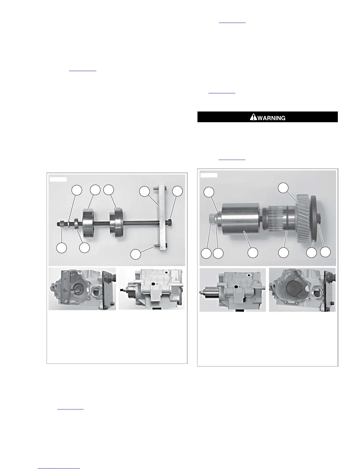
Installing Main Drive Gear
NOTE
See Figure 7-45. Make sure to install new o-ring (4) onto main
drive gear (3) and lubricate o-ring with clean engine oil before
installing drive gear into transmission case.
1. See Figure 7-45. Insert 8 IN. BOLT (Part No. HD-35316-
4A) (1) through WASHER (Part No. HD-35316-7) (2) and
main drive gear (3). Insert assembly into transmission
case, through main drive gear bearing.
2. At outside of case, place INSTALLER CUP (Part No. HD-
35316-12) (5), BEARING (Part No. 217801) (6), FLAT
WASHER (7) and NUT (8) over end of bolt. Tighten nut
until main drive gear bottoms against main drive gear
bearing.
NOTE
See Figure 7-46. In next step, bearing retaining ring must be
installed with the flat side facing the bearing and the opening
in the ninety degree window as shown.
Wear safety glasses or goggles when removing or
installing retaining rings. Retaining rings can slip from the
pliers and could be propelled with enough force to cause
serious eye injury. (00312a)
3. See Figure 7-47. Install new retaining ring (2).
 Loading...