8.27MAIN WIRING HARNESS
GENERAL
The main wiring harness is routed through the frame backbone
and has enough slack designed into it so that it can be pulled
out of the front end of the backbone to access the connectors
located inside the frame.
NOTE
See B.1 CONNECTORS, Connector Locations for a description
of all connector locations.
REMOVAL
1. Remove seat.
Disconnect negative (-) battery cable first. If positive (+)
cable should contact ground with negative (-) cable con-
nected, the resulting sparks can cause a battery explosion,
which could result in death or serious injury. (00049a)
NOTE
Disarm HFSM or TSSM before removal.
2. Disconnect battery cables, negative cable first.
3. Remove battery.
4. Remove battery tray. See 8.8 BATTERY TRAY AND
BATTERY CABLES.
5. Remove instrument console.
a. For FXDWG/FXDC/FXDF models, see
8.17 INSTRUMENTS: FXDWG/FXDC/FXDF.
b. For FXDL, FXDB models, see 8.18 INSTRUMENTS:
FXDL/FXDB.
c. For FXD models, see 8.15 FUEL GAUGE.
NOTE
To ensure proper installation, make note of all wire routing and
connector locations before removal. In particular, pay close
attention to the locations of cable straps and anchors which
must be replaced.
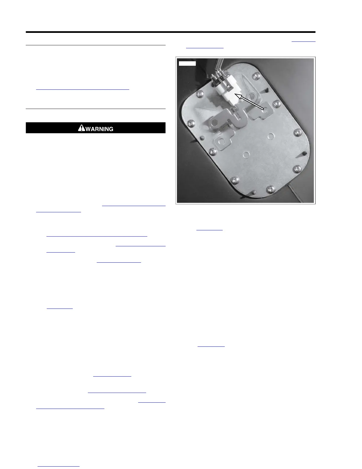
6. See Figure 8-71. Disconnect fuel pump/sender connector
[141].
7. For FXDWG/FXDC/FXDF models, remove the remaining
three main harness connectors. The three are:
a. Key switch [33].
b. Indicator lamps [21] (8-Place Mini-Deutsch).
c. Speedometer [39] (NOTE: Reset boot and switch
must be removed from console).
8. Remove fuel tank. See 4.5 FUEL TANK. This includes
detaching fuel gauge connector [117].
9. Remove exhaust. See 4.16 EXHAUST SYSTEM.
10. Remove rear brake master cylinder. See 2.14 REAR
BRAKE MASTER CYLINDER.
11. On HDI vehicles, remove active exhaust module connector
[179] located in front of electrical caddy.
12. Remove electrical caddy and ignition coil. See 8.2 ELEC-
TRICAL CADDY.
Figure 8-71. Fuel Pump Connector [141] (typical)
13. See Figure 8-72. Remove harness shield by pushing both
tabs of shield in at the same time.
14. Pull harness connectors from inside frame.
15. Disconnect the following connectors:
a. Right handlebar controls [22] (6-place Deutsch).
b. Left handlebar controls [24] (6-Place Deutsch).
c. Instruments [20].
d. Turn signals [31].
e. (FXDL/FXDB models) Instruments [21].
f. Headlamp [38].
NOTE
In next step, note location of ground wires before removal to
ensure proper installation.
16. See Figure 8-73. Remove ground wires from studs on
frame.
17. Disconnect connectors located under seat:
a. Accessory connector [4].
b. Tail lamp harness connector [7].
c. Rear oxygen sensor [137].
d. Security siren connector [142] if security siren
installed.
e. B+ connector [160].
18. Disconnect starter solenoid [128].
8-48 2008 Dyna Service: Electrical