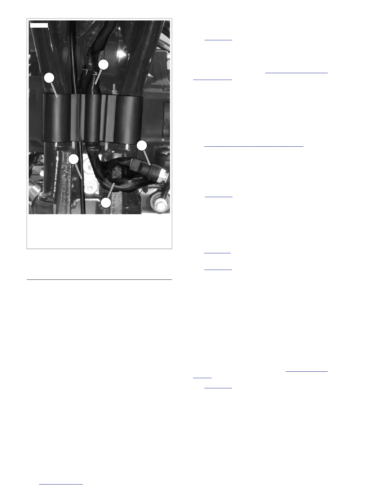
1. Wire harness retainer
2. Vent line
3. To front of vehicle
4. Rear brake light switch
5. Front engine harness
Figure 8-74. Main Wire Harness (Typical)
INSTALLATION
NOTES
• Be sure to replace all cable straps and anchors.
• Do not remove factory installed wire harness tape securing
connectors to harness unless necessary.
1. Guide wiring harness back into frame backbone. Pull the
front of the harness through using the guide wire while
pushing the harness through the frame tube opening.
2. Connect the following connectors.
a. Right handlebar controls [22] (6-place Deutsch).
b. Left handlebar controls [24] (6-Place Deutsch).
c. Instruments [20].
d. Turn signals [31].
e. (FXDL/FXDB models) Instruments [21].
f. Headlamp [38].
NOTE
Be sure to leave enough slack in harness at front of vehicle so
when front wheel is turned, harness does not bind.
3. Install connectors into frame. Install harness shield.
4. To ease installation, wrap voltage regulator terminals with
electrical tape.
5. See Figure 8-74. Route engine harness (which contains
voltage regulator connector [77], crank position sensor
connector [79], stator connector [46] and front oxygen
sensor [138] wiring to front of vehicle as shown. Install the
oxygen sensor and crank position sensor connectors in
front electrical caddy (see 8.13 CRANK POSITION
SENSOR (CKP)). Connect the engine harness and stator
connectors to the voltage regulator.
6. Route rear brake switch wiring (4) as shown and connect
to rear brake switch.
7. Route neutral switch wiring and connect to neutral switch.
8. Route starter solenoid wiring and connect to starter
solenoid.
9. Install rear brake master cylinder and rear brake control.
See 2.14 REAR BRAKE MASTER CYLINDER.
10. Secure front engine harness with harness clamps.
11. Install wire harness retainer (1).
12. Connect rear fender extension to rear fender.
NOTES
• See Figure 8-74. To prevent contact with rear fork, front
engine harness (5) and rear brake switch wiring must be
secured in wire harness retainer (1).
• If equipped with jiffy stand sensor (HDI models only), route
the sensor harness up along the vent line (2) and secure
in the same retainer cavity as the vent line.
13. Connect oil pressure switch [120].
14. See Figure 8-75. Connect vehicle speed sensor connector
[65].
15. See Figure 8-76. Secure harness grounds to studs.
16. Route top engine harness to fuel tank area.
17. Connect:
a. MAP sensor connector [80].
b. Horn wires.
c. IAT sensor connector [89].
d. ET sensor connector [90].
e. IAC connector [87].
f. TP sensor connector [88].
g. Front [84] and rear [85] fuel injector connectors.
18. Install electrical caddy and wiring. See 8.2 ELECTRICAL
CADDY.
19. See Figure 8-78. Mate connectors located under seat:
a. Accessory connector [4].
b. Tail lamp harness connector [7].
c. Rear oxygen sensor [137].
d. Security siren connector [142] if security siren
installed.
e. B+ connector [160].
8-50 2008 Dyna Service: Electrical
 Loading...