8.28HANDLEBAR SWITCH ASSEMBLIES
GENERAL
The switches are of rugged construction and feature a superior
seal to protect electrical contacts and components from dirt
and moisture in harsh environments.
The left handlebar switches include the headlamp HI - LO
switch, horn and left turn signal switch. The right handlebar
switches include the engine start and RUN - OFF switch and
right turn signal switch. The individual switches are non-
repairable and must be replaced if they malfunction.
NOTES
• On certain models, the turn signal wiring is routed through
the lower switch housings and handlebars.
• To replace or repair individual switches in either the right
or left handlebar switch assemblies, see 8.29 RIGHT
HANDLEBAR SWITCH or 8.30 LEFT HANDLEBAR
SWITCH.
REPAIR PROCEDURES
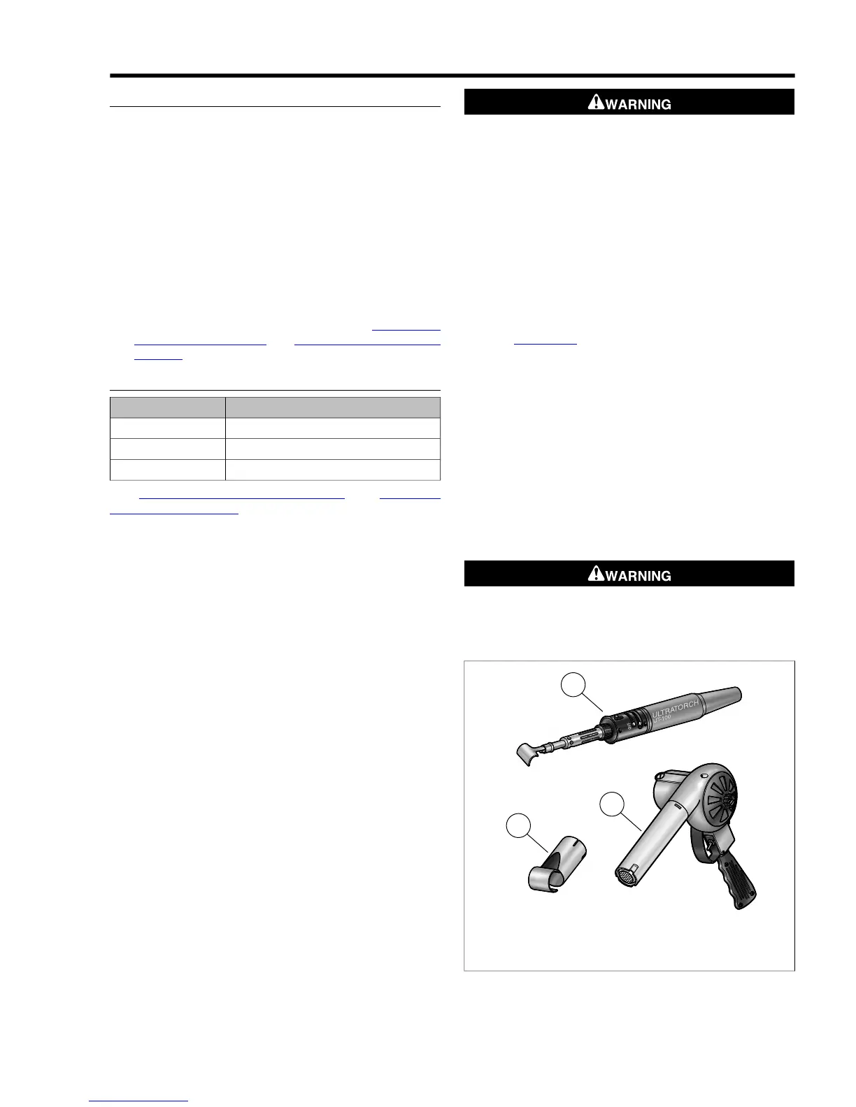
TOOL NAMEPART NUMBER
ROBINAIR HEAT GUNHD-25070
ULTRA TORCH UT-100HD-39969
HEAT SHIELD ATTACHMENTHD-41183
See 8.29 RIGHT HANDLEBAR SWITCH and 8.30 LEFT
HANDLEBAR SWITCH. The removal and installation steps
listed apply when replacing the entire switch assembly, switch
housing or handlebars.
The information below is useful when repairing handlebar
switch assemblies.
1. To better access wires and avoid damaging conduit with
radiant heating device, push conduit back and secure with
extra 7.0 in. (177.8 mm) cable strap in kit.
2. Strip 0.5 in (12.7 mm) of insulation off switch wires.Twist
stripped ends of switch wires until all strands are tightly
coiled.
3. Cut dual wall heat-shrink tubing, supplied in repair kit into
1.0 in. (25.4 mm) segments. Slide tubing over each wire
of new switch assembly.
4. Splice existing and new switch wires, matching wire colors.
Solder the spliced connections. For best results, do one
wire at a time.
5. Center the heat-shrink tubing over the soldered splices.
Be sure to follow manufacturer's instructions when using
the UltraTorch UT-100 or any other radiant heating device.
Failure to follow manufacturer's instructions can cause a
fire, which could result in death or serious injury. (00335a)
• Avoid directing heat toward any fuel system component.
Extreme heat can cause fuel ignition/explosion resulting
in death or serious injury.
• Avoid directing heat toward any electrical system com-
ponent other than the connectors on which heat shrink
work is being performed.
• Always keep hands away from tool tip area and heat shrink
attachment.
6. See Figure 8-79. Using the ULTRA TORCH UT-100 (Part
No. HD-39969) or ROBINAIR HEAT GUN (Part No. HD-
25070) with HEAT SHIELD ATTACHMENT (Part No. HD-
41183) or other suitable radiant heating device, uniformly
heat the heat-shrink tubing to insulate and seal the
soldered connections. Apply heat just until the meltable
sealant exudes out both ends of tubing and it assumes a
smooth cylindrical appearance.
7. Inspect the melted sealant for solder beads. Excess solder
or heat may force some solder out with the melted sealant.
Use a small needle nose pliers to remove any solder
found. Briefly heat the connection to reseal the tubing if
solder beads were removed. Use less solder or reduce
heating time or intensity when doing subsequent splices.
Be sure that all lights and switches operate properly before
operating motorcycle. Low visibility of rider can result in
death or serious injury. (00316a)
 Loading...