8.29RIGHT HANDLEBAR SWITCH
REMOVAL
NOTE
The removal and installation steps listed apply when replacing
the entire switch assembly, switch housing or handlebars.
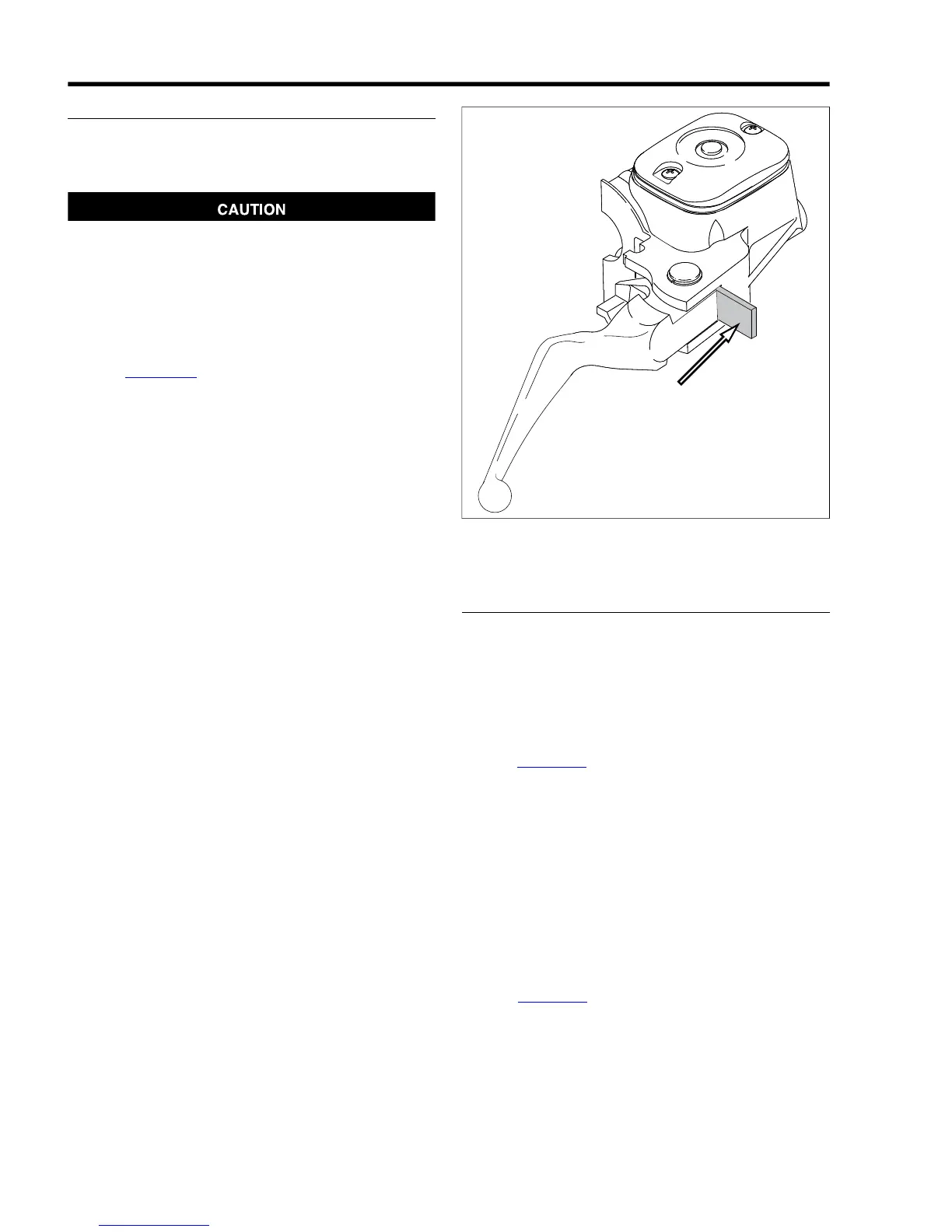
Do not remove or install the master cylinder assembly
without first positioning a 5/32-inch (4 mm) thick insert
between the brake lever and lever bracket. Removing or
installing the master cylinder assembly without the insert
in place may result in damage to the rubber boot and
plunger on the front stoplight switch. (00324a)
1. Remove maxi-fuse.
2. See Figure 8-80. Place the 5/32 in. (4 mm) thickness
cardboard insert between the brake lever and lever
bracket.
3. Using a T27 TORX drive head, remove the two screws
with flat washers securing the handlebar clamp to the
master cylinder housing. Remove the brake lever/master
cylinder assembly and clamp from the handlebar.
4. Using a T25 TORX drive head, remove the upper and
lower switch housing screws.
5. Remove the friction shoe from the end of the tension
adjuster screw.
NOTE
The friction screw is a loose fit and may fall out or become
dislodged if the lower switch housing is turned upside down or
shaken.
6. Remove the brass ferrules from the notches on the inboard
side of the throttle control grip. Remove the ferrules from
the cable end fittings.
7. Remove the throttle control grip from the end of the
handlebar.
8. Pull the crimped inserts at the end of the throttle and idle
control cable housings from the lower switch housing. For
best results, use a rocking motion while pulling. Place a
drop of light oil on the retaining rings, if necessary.
Remove the cables from the switch housing.
Figure 8-80. Install 5/32 in. (4 mm) Thickness Cardboard
Insert
INSTALLATION
1. With the concave side facing upward, install the friction
shoe so that the pin hole is over the point of the adjuster
screw.
NOTE
The friction shoe is a loose fit and may fall out or become dis-
lodged if the lower switch housing is turned upside down or
shaken.
2. See Figure 8-81. Push the throttle and idle control cables
into the lower switch housing until they snap in place. Note
the different diameter inserts crimped into the end of the
throttle and idle cable housings.
a. Push the silver insert (2) of throttle cable housing into
the hole in front of tension adjuster screw (3).
b. Push the gold insert (1) of idle cable housing into the
hole at the rear of tension adjuster screw (3).
NOTE
To aid assembly, place a drop of light oil on the retaining rings
of the crimped inserts. Always replace the retaining rings if
damaged or distorted.
3. See Figure 8-82. Route the cable (2) to the upper switch
housing as shown.
4. Slide the throttle control grip over the end of the right
handlebar until it bottoms against the closed end. Rotate
the grip so that the ferrule notches are at the top. To pre-
vent binding, pull the grip back about 1/8 in. (3.2 mm).
8-54 2008 Dyna Service: Electrical
 Loading...