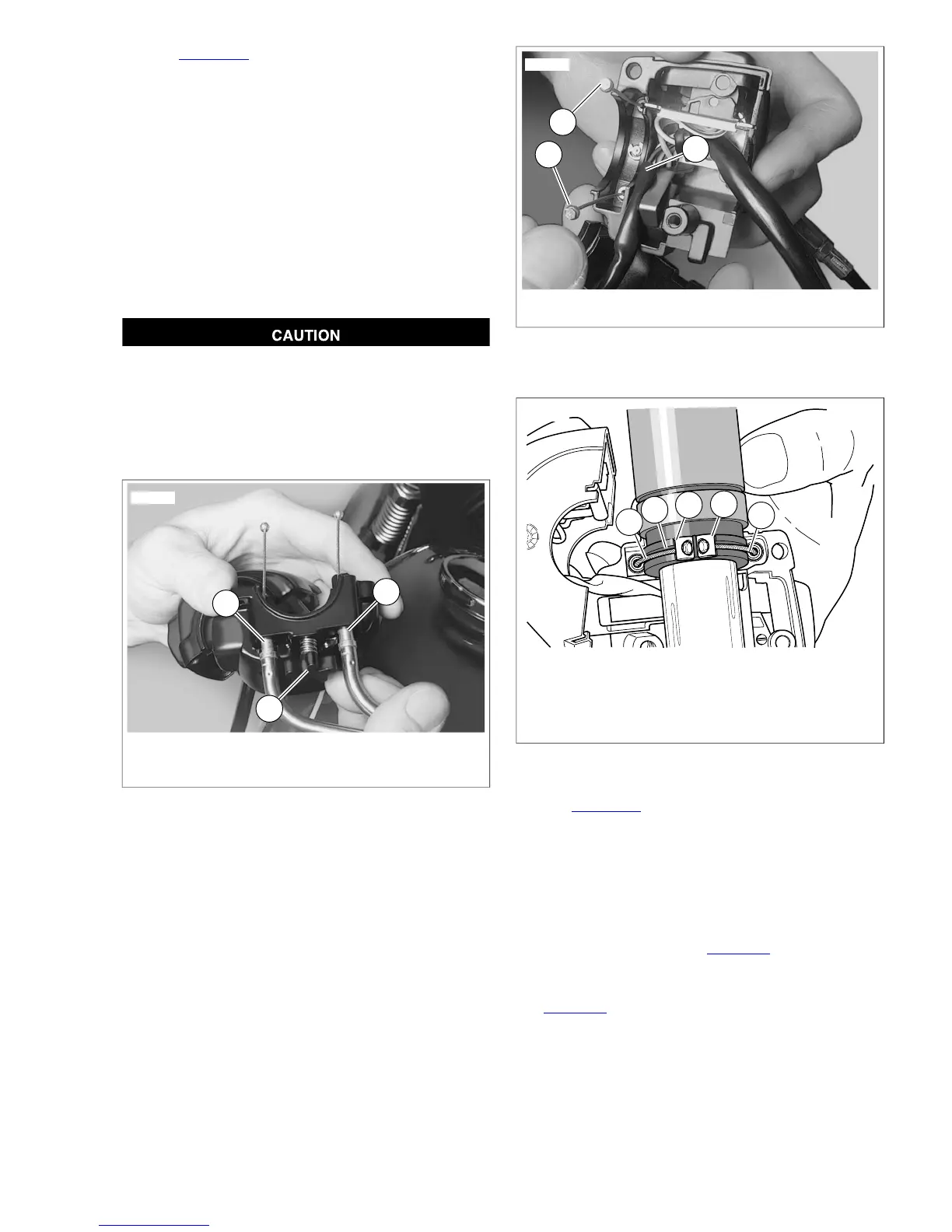
5. See Figure 8-83. Position lower switch housing beneath
the throttle control grip. Install the brass ferrules (4) onto
the cable so that the end fittings seat in the ferrule recess.
Seat the ferrules in their respective notches (3) on the
throttle control grip. Verify that the cables are captured in
the grooves (2) molded into the grip.
6. Position the upper switch housing over the handlebar and
lower switch housing.
7. Verify that the wire harness conduit runs in the depression
at the bottom of the handlebar. Be sure that the upper
switch housing harness will not be pinched under the
handlebar when the switch housing screws are tightened.
8. Start the upper and lower switch housing screws, but do
not tighten.
Do not remove or install the master cylinder assembly
without first positioning a 5/32-inch (4 mm) thick insert
between the brake lever and lever bracket. Removing or
installing the master cylinder assembly without the insert
in place may result in damage to the rubber boot and
plunger on the front stoplight switch. (00324a)
1. Idle cable insert (gold insert, rear hole)
2. Throttle cable insert (silver insert, front hole)
3. Tension adjuster screw
Figure 8-81. Right Lower Switch Housing
1. End fittings
2. Upper switch housing cable
Figure 8-82. Route Cable to Upper Switch Housing
1. Throttle cable (silver insert, front hole)
2. Groove in throttle grip
3. Notch
4. Brass ferrule
5. Idle cable (gold insert, rear hole)
Figure 8-83.Throttle Cable Attachment
9. See Figure 8-84. Position the brake lever/master cylinder
assembly inboard of the switch housing assembly, enga-
ging the tab (2) on the lower switch housing in the groove
(3) at the top of the brake lever bracket.
10. Align the holes in the handlebar switch clamp with those
in the master cylinder housing and start the two screws
(with flat washers). Position for rider comfort. Beginning
with the top screw, tighten to specification using a T27
TORX drive head. Refer to Table 8-10.
11. Using a T25 TORX drive head, tighten lower and upper
switch housing screws to specification. Refer to
Table 8-10.
NOTE
Always tighten the lower switch housing screw first so that any
gap between the upper and lower housings is at the front of
the switch.
2008 Dyna Service: Electrical 8-55
 Loading...