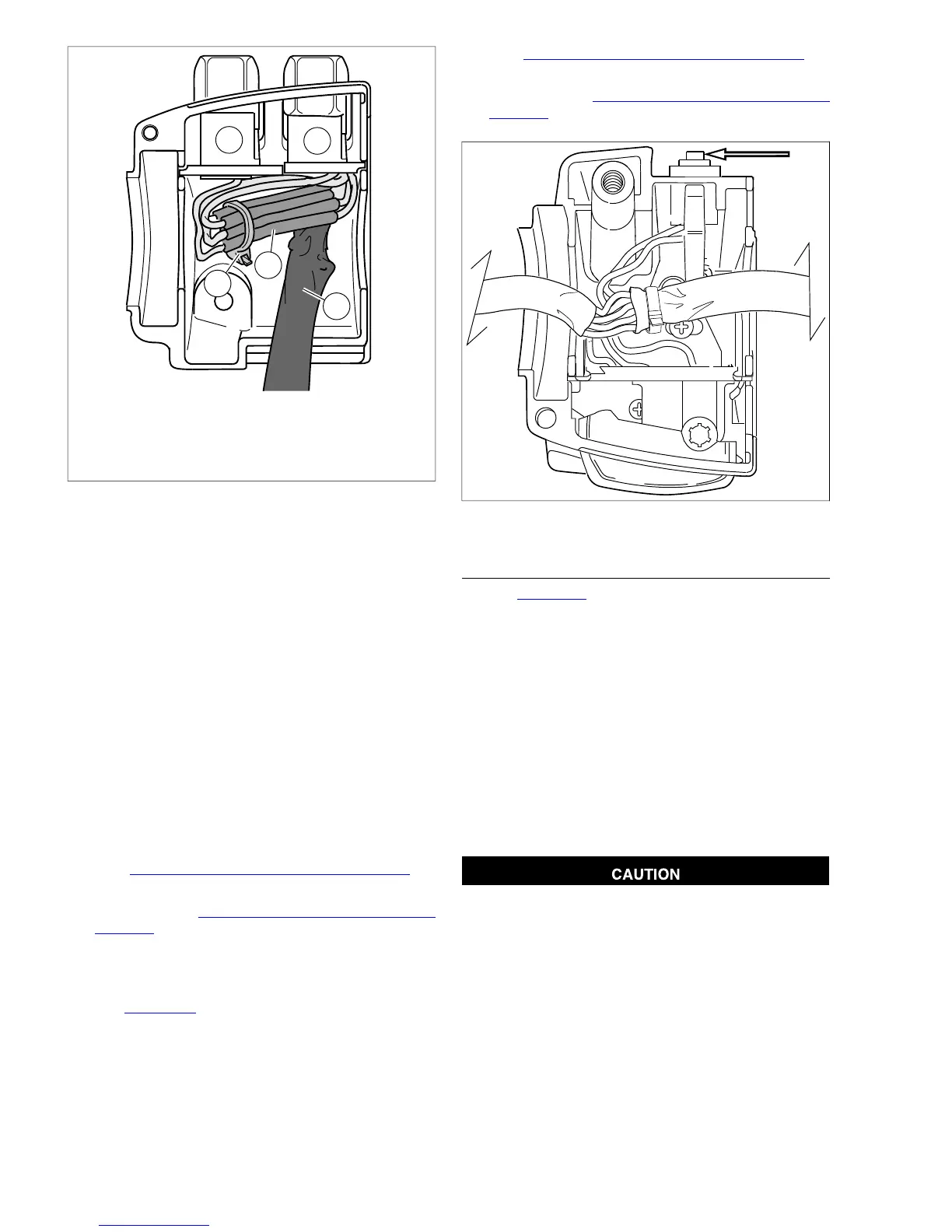
1. Horn switch
2. High/low beam switch
3. Conduit
4. Splices
5. Cable strap
Figure 8-93. Upper Housing With Splices
Lower Housing Repair
1. From inside the switch housing, carefully cut cable strap
to free conduit from the turn signal switch bracket.
2. Remove screw with lockwasher to release the turn signal
switch bracket. Remove the bracket and switch assembly
from the housing.
3. Continue with TURN-LEFT SIGNAL SWITCH or CLUTCH
INTERLOCK SWITCH procedures.
Turn-Left Signal Switch
1. Perform steps in LOWER HOUSING REPAIR.
2. Cut wires 1.5 in. (38.1 mm) from old switch (Turn-L(eft)
Signal Switch). Discard switch assembly.
NOTE
Replacement turn-right signal switch wires are cut to length of
1.5 in. (38.1 mm) and partially stripped.
3. See 8.28 HANDLEBAR SWITCH ASSEMBLIES for
information on splicing and general repair practices.
4. Continue with 8.30 LEFT HANDLEBAR SWITCH,
Assembly.
Clutch Interlock Switch
1. Perform steps in LOWER HOUSING REPAIR.
2. See Figure 8-94. Cut wires 0.25 in. (6.4 mm) from old
switch. Discard switch assembly.
NOTE
Replacement turn-right signal switch wires are cut to length
and partially stripped.
3. See 8.28 HANDLEBAR SWITCH ASSEMBLIES for
information on splicing and general repair practices.
4. Continue with 8.30 LEFT HANDLEBAR SWITCH,
Assembly.
Figure 8-94. Clutch Interlock Switch
ASSEMBLY
1. See Figure 8-95. Insert tapered end of new 7.0 in. (177.8
mm) cable strap (1) into round hole in turn signal switch
bracket (2) and then feed back through using the adjacent
hole. Reserve the oblong hole for the bracket screw.
NOTE
Be sure that all splices are positioned above the turn signal
switch bracket.
2. Place the turn signal switch assembly (3) into the housing,
aligning the oblong hole in the bracket with the threaded
hole in the boss. Be sure that the bracket is fully seated.
Tabs on each side of bracket are captured in slots cast
into switch housing.
3. Start screw with lockwasher to secure bracket inside
housing.
If routed incorrectly, wires can be pinched by casting or
handlebar resulting in switch failure. (00542b)
4. Loop switch wires so that spliced lengths are positioned
across bracket.
5. Capturing conduit about 0.25 in. (6.4 mm) from end,
securely tighten cable strap to draw conduit to bracket.
Remove any excess cable strap material.
6. Tighten screw to secure bracket inside housing.
7. Route wire bundle to upper switch housing below and then
forward of the main wire harness, positioning conduit in
channel next to angular arm of bracket. Secure bundle to
8-62 2008 Dyna Service: Electrical



 To Next Page