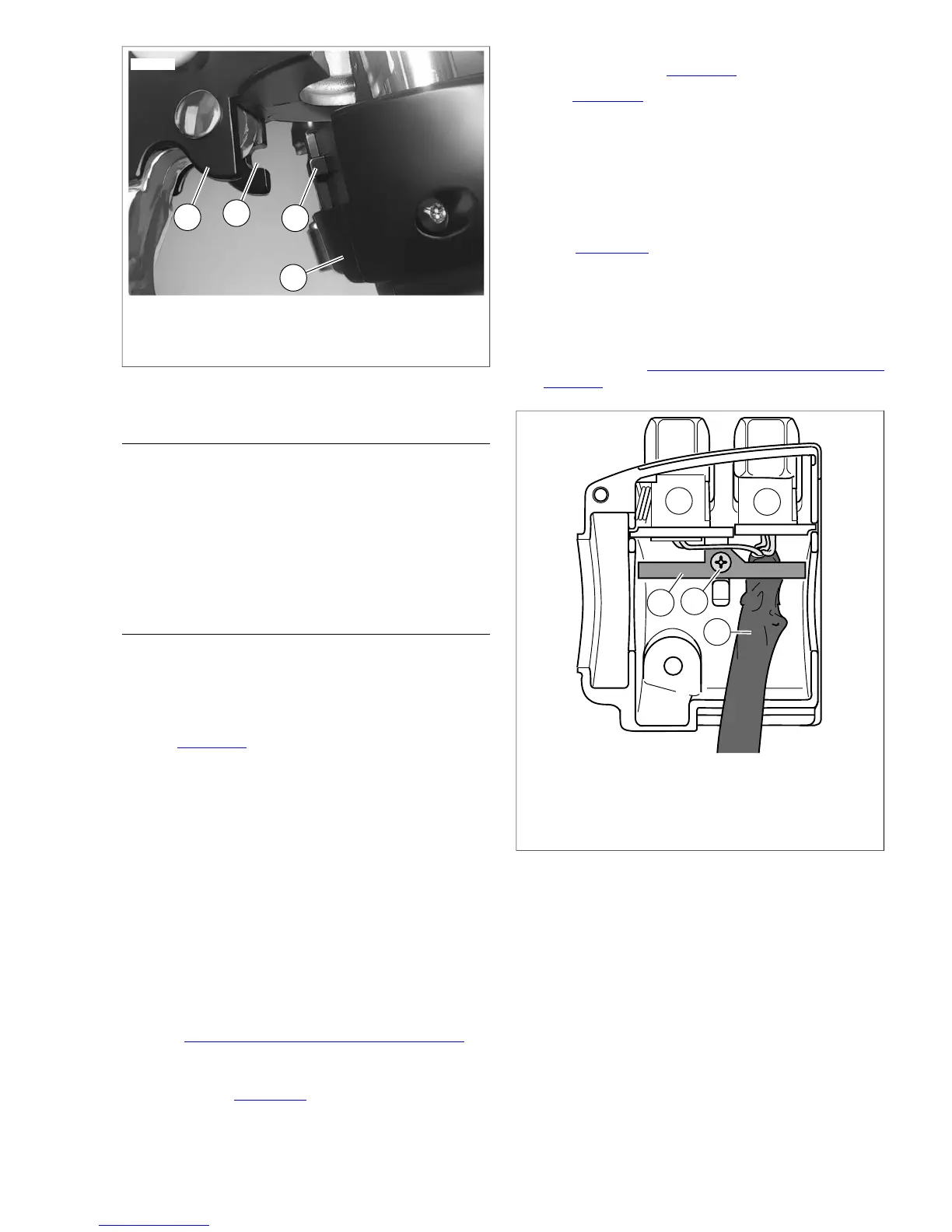
1. Clutch lever bracket
2. Groove
3. Tab
4. Switch housing assembly
Figure 8-91. Clutch Lever Bracket
DISASSEMBLY
1. Using a T25 TORX drive head, remove the upper and
lower switch housing screws.
2. If replacing lower housing switches, perform next step
before continuing to repair section. If replacing upper
housing switches, proceed directly to repair section.
3. Using a T27 TORX drive head, loosen the upper screw
securing the handlebar clamp to the clutch lever bracket.
Remove the lower clamp screw with flat washer.
SWITCH REPAIR/REPLACEMENT
Upper Housing Repair
NOTE
Replace the horn switch and high/low beam switch as a single
assembly even if only one switch is determined to be faulty.
1. See Figure 8-92. From inside the switch housing, remove
the screw with lockwasher (4) to release the bracket (5).
Remove bracket and switch assembly from the housing.
2. Move cable conduit (3) from beneath wing of bracket. Cut
wires 0.25 in. (6.4 mm) from old switches (1, 2). Discard
old switch and bracket assembly.
3. Slide conduit forward over cut ends of switch wires and
cut off 0.5 in. (12.7 mm) of conduit (3) material. Push
conduit back to access switch wires.
4. Separate the new horn switch (1) and high/low beam
switch (2) wires into two bundles.
NOTE
Replacement high/low beam switch and horn switch wires are
cut to length of 2.5 in. (63.5 mm) and 2.0 in. (50.8 mm)
respectively, and partially stripped.
5. See 8.28 HANDLEBAR SWITCH ASSEMBLIES for
information on splicing and general repair practices.
6. Loop switch wires so that spliced lengths are positioned
as shown in Figure 8-93. Route wires downstream of
splices beneath wing on high/low beam switch side of
bracket as shown in Figure 8-92.
7. See Figure 8-93. Install a new 7.0 in. (177.8 mm) cable
strap (5) beneath wing on horn switch side (1) of bracket
and capture wire splices (4).
8. Place switch assembly into upper housing aligning hole
in bracket with threaded hole in boss. Be sure that bracket
is fully seated. The step at the edge of the boss captures
the bottom edge of the bracket, while tabs on each side
of the bracket fit in slots cast into the housing.
9. See Figure 8-92. Install screw and lockwasher (4) to
secure bracket (5) inside housing. Verify that wing on
high/low switch (2) side of bracket captures edge of conduit
(3) as shown.
10. Securely tighten cable strap to draw splices to bracket.
Remove any excess cable strap material.
11. Continue with 8.30 LEFT HANDLEBAR SWITCH,
Assembly.
 Loading...