8.30LEFT HANDLEBAR SWITCH
REMOVAL
NOTE
The removal and installation steps listed apply when replacing
the entire switch assembly, switch housing or handlebars.
To prevent accidental vehicle start-up, which could cause
death or serious injury, remove maxi-fuse before pro-
ceeding. (00251a)
1. Remove maxi-fuse. See 8.6 FUSES AND RELAYS.
2. Using a T27 TORX drive head, remove the two screws
with flat washers securing the handlebar clamp to the
clutch lever bracket. Remove the clutch hand lever
assembly and clamp from the handlebar.
3. Using a T25 TORX drive head, remove the upper and
lower switch housing screws.
4. Remove the grip sleeve from the end of the handlebar if
damaged.
INSTALLATION
1. If the grip sleeve was removed, thoroughly clean handlebar
to remove all adhesive residue. Pour adhesive into new
grip. Roll grip to evenly distribute adhesive on inside sur-
faces. Install grip on handlebar with a twisting motion.
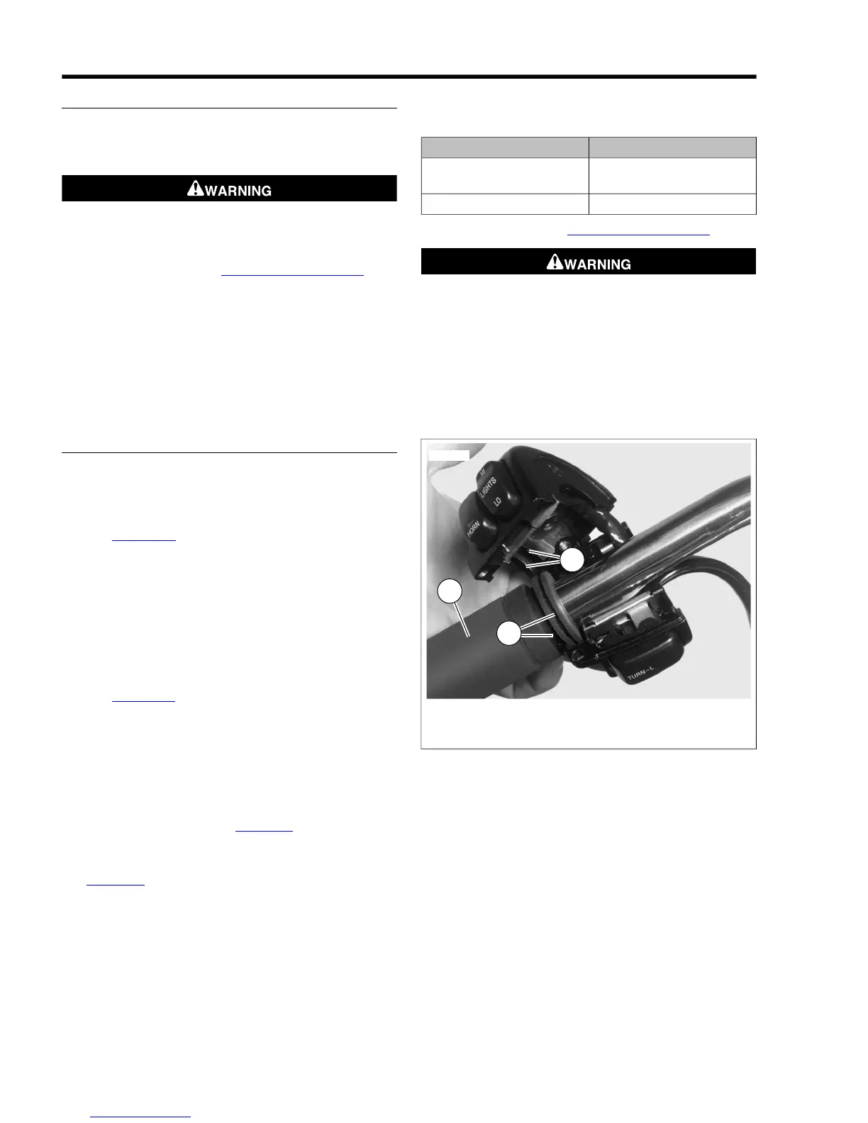
2. See Figure 8-90. Install upper and lower switch housings
on handlebar. Be sure that ribs (2) on outboard side of
switch housings fit in grooves (3) molded into grip.
3. Verify that the wire harness conduit runs in the groove at
the bottom of the handlebar. Be sure that the upper switch
housing harness will not be pinched under the handlebar
when the switch housing screws are tightened.
4. Start the upper and lower switch housing screws, but do
not tighten.
5. See Figure 8-91. Position the clutch hand lever assembly
inboard of the switch housing assembly, engaging the tab
(3) on the lower switch housing in the groove (2) at the
bottom of the clutch lever bracket.
6. Align the holes in the handlebar switch clamp with those
in the clutch lever bracket and start the two screws (with
flat washers). Position for rider comfort. Beginning with
the top screw, tighten screws to specification with a T27
TORX drive head. Refer to Table 8-11.
7. Using a T25 TORX drive head, tighten lower and upper
switch housing screws to specification. Refer to
Table 8-11.
NOTE
Always tighten the lower switch housing screw first so that any
gap between the upper and lower housings is at the front of
the switch.
Table 8-11. Handlebar Switch Assembly Fasteners: Dyna
Models
TORQUEFASTENER
60-80 in-lbs (6.8-9.0 Nm)Handlebar switch clamp
screws
35-45 in-lbs (4.0-5.1 Nm)Switch housing screws
8. Install maxi-fuse. See 8.6 FUSES AND RELAYS.
Be sure that all lights and switches operate properly before
operating motorcycle. Low visibility of rider can result in
death or serious injury. (00316a)
9. Test the switches for proper operation.
10. If necessary, secure wire harness conduit to handlebar
using new cable strap. Position cable strap approximately
4-5 in. (100-127 mm) from handlebar clamp. Cut any
excess cable strap material.