A.10MOLEX CONNECTORS
MOLEX CONNECTOR REPAIR
TOOL NAMEPART NUMBER
MOLEX ELECTRICAL CONNECTOR
TERMINAL REMOVER
HD-48114
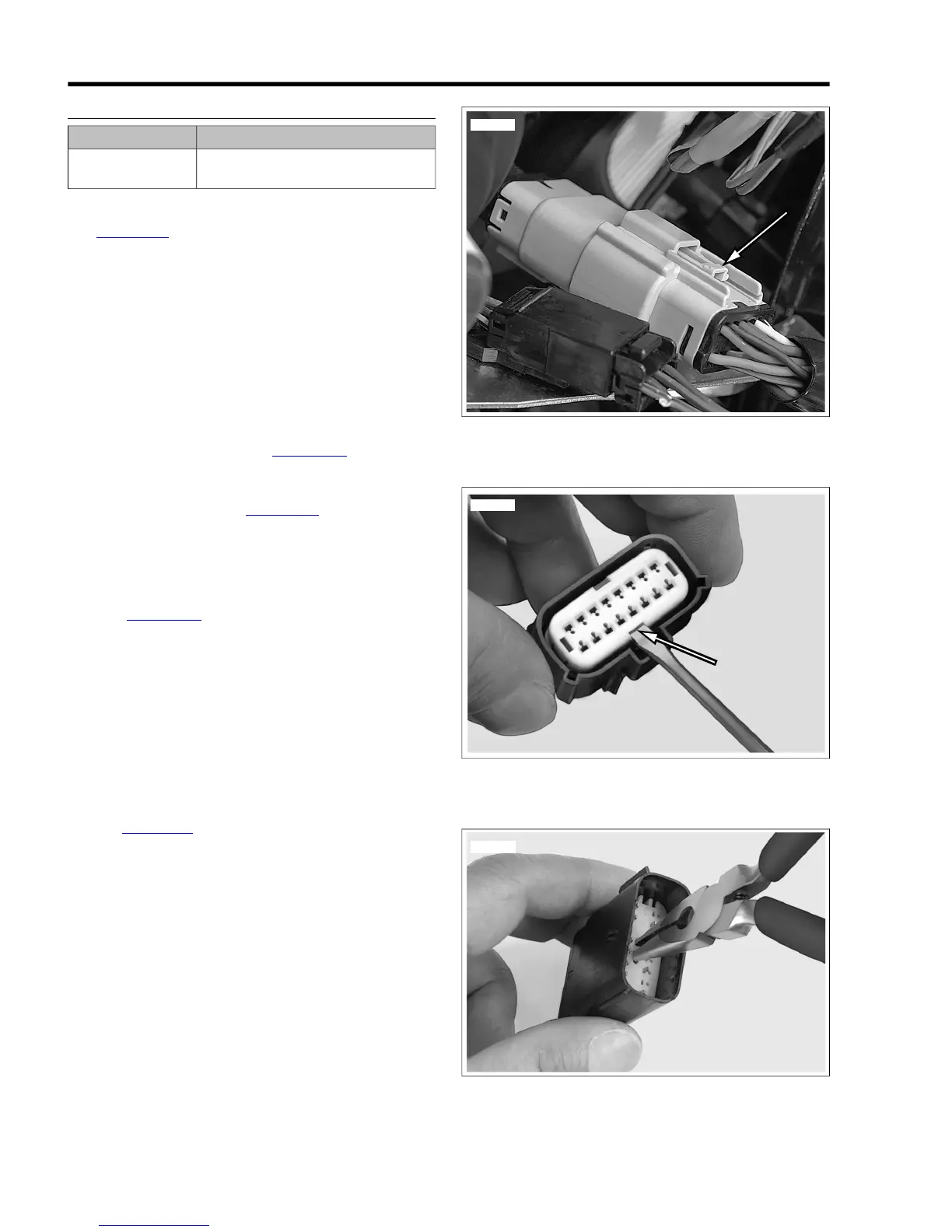
Separating Pin and Socket Housings
See Figure A-27. Depress the latch while pulling the pin and
socket housings apart.
Mating Pin and Socket Housings
1. Orient the latch on the pin housing to the latch pocket on
the socket housing so the rails on the outside of the pin
housings lines up with the tunnels on the socket housing.
2. Press the housings together until the latch clicks.
Removing Terminals
1. Pull the secondary lock up, approximately 3/16 in. (4.8
mm), until it stops.
a. Socket Housing: See Figure A-28. Use a small
screwdriver in the pry slot. The slot next to the
external latch provides a pivot point.
b. Pin Housing: See Figure A-29. Use needle nose
pliers to engage the D-holes in the center of the sec-
ondary lock.
NOTE
Do not remove the secondary lock from the connector housing.
2. See Figure A-30. Insert MOLEX ELECTRICAL CON-
NECTOR TERMINAL REMOVER (Part No. HD-48114)
into the pin hole next to the terminal until the tool bottoms.
a. Socket Housing: The pin holes are inside the ter-
minal openings.
b. Pin Housing: The pin holes are outside the pins.
3. Pressing the terminal remover to the bottom of the pin
hole, gently pull on the wire to remove wire terminal from
its cavity.
Installing Terminals
1. See Figure A-31. From the wiring diagram, match the wire
color to its numbered terminal cavity.
NOTE
Cavity numbers (1) are stamped on the housing at the ends
of the cavity rows. The cavity number can be determined by
counting the cavities up or down along the row from each
stamped number.
2. Orient the terminal so that the tang (2) opposite the open
crimp engages the slot (3) in the cavity.
3. Push the terminal into the cavity.
4. Gently tug on wire to verify that the terminal is captured
by the secondary lock.
5. With all terminals installed, push the secondary lock into
the socket housing to lock the wire terminals into the
housing.
 Loading...