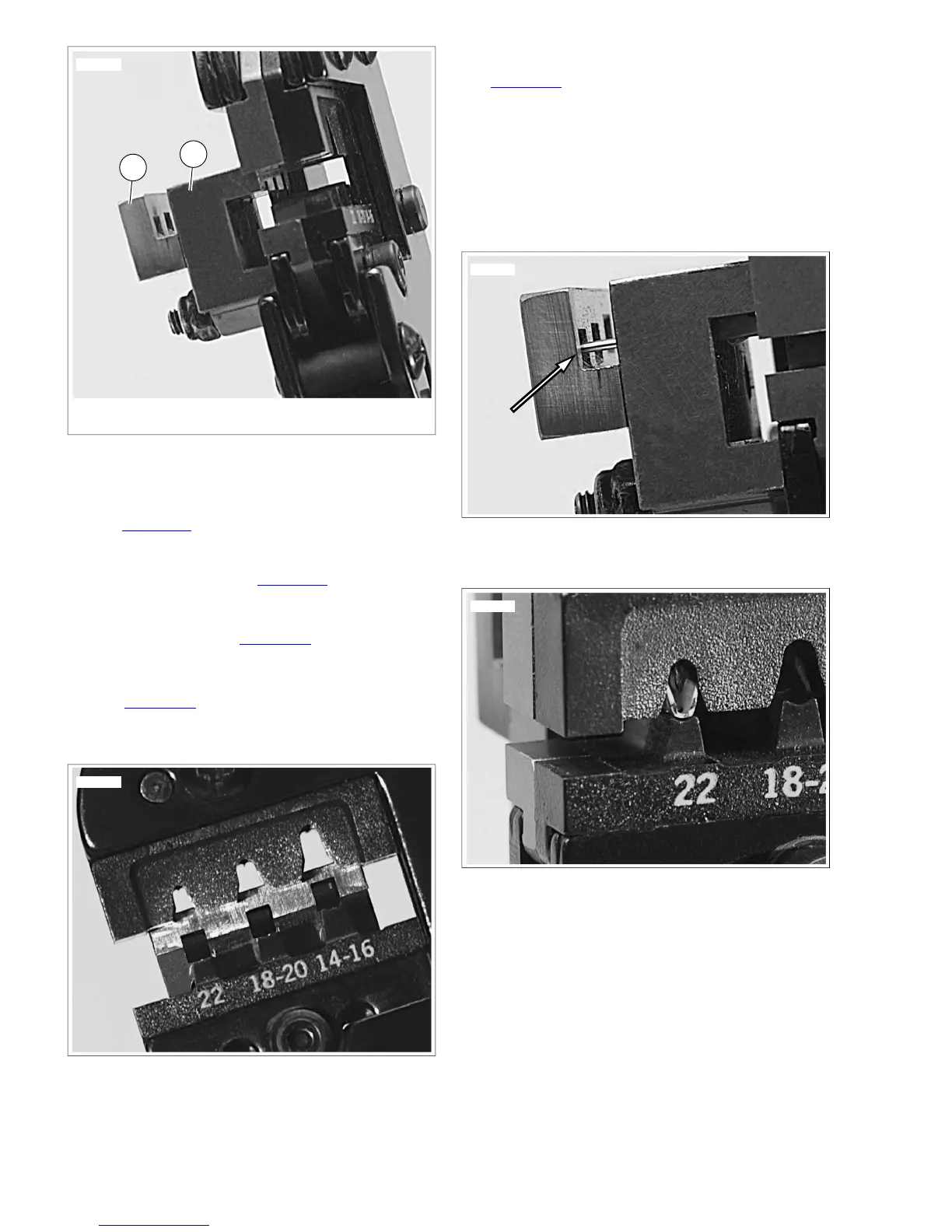
1. Socket locator bar
2. Pin locator bar
Figure A-33.Terminal Locator Bars
Position Terminal in the Punch/Die
1. See Figure A-34.With the crimp tails up, place the terminal
through the punch/die into the square opening in the
socket locator bar.
a. Socket Terminal: See Figure A-33. A socket terminal
stops against the back face of the socket locator bar
(1).
b. Pin Terminal: See Figure A-35. The tip of a pin ter-
minal passes through the socket locator bar and stops
in the notch in the face of the pin locator bar.
2. See Figure A-36. Ratchet the handles together until the
crimp tails are held in vertical alignment between the punch
and the die.
Figure A-34. Square Openings in Socket Locator Bar
Insert Stripped Lead
See Figure A-37. Insert the stripped end (wire core) between
the crimp tails at an up angle until the wire core touches the
face of the socket locator bar above the square opening.
NOTES
• The insulation must extend through the insulation crimp
tails.
• Insert the wire with little or no pressure. Pressing on the
lead will bend the wire core.
Figure A-35. Pin Terminal against Pin Locator Bar
Figure A-36. Crimp Tails in Vertical Alignment between
Punch and Die
Crimp Terminal to Lead
1. Holding the wire lead in position touching the locator face
at an angle, quickly and smoothly squeeze the crimp tool
closed.
2. Final squeeze the handles to open the tool and release
the terminal.
A-22 2008 Dyna Service: Appendix A Connector Repair
 Loading...