A.17PACKARD MICRO-64 CONNECTORS
PACKARD MICRO-64 CONNECTOR REPAIR
TOOL NAMEPART NUMBER
PACKARD MICRO-64 TERMINAL
REMOVER
HD-45928
PACKARD MICRO-64 TERMINAL
CRIMPER
HD-45929
General
Packard Micro-64 connectors are frequently found on
speedometers, tachometers and the ECM of Touring Models.
For pin 73 of these ECMs, see A.11 PACKARD 150 METRI-
PACK CONNECTORS.
Separating Pin and Socket Housings
Bend back the external latches slightly and separate the pin
and socket housings.
Mating Pin and Socket Housings
Orient the wire lead colors and push the pin and socket hous-
ings of the connector together until the latches click.
Removing Terminal
1. See Figure A-51. Locate the head of the secondary lock
(1) on one side of the connector housing.
2. Insert the blade of a small screwdriver between the center
ear of the lock and the connector housing and gently pry
out lock.When partially removed, pull lock from connector
housing.
3. Locate pin hole (2) between terminals on mating end of
connector.
4. See Figure A-52. Obtain the PACKARD MICRO-64 TER-
MINAL REMOVER (Part No. HD-45928).
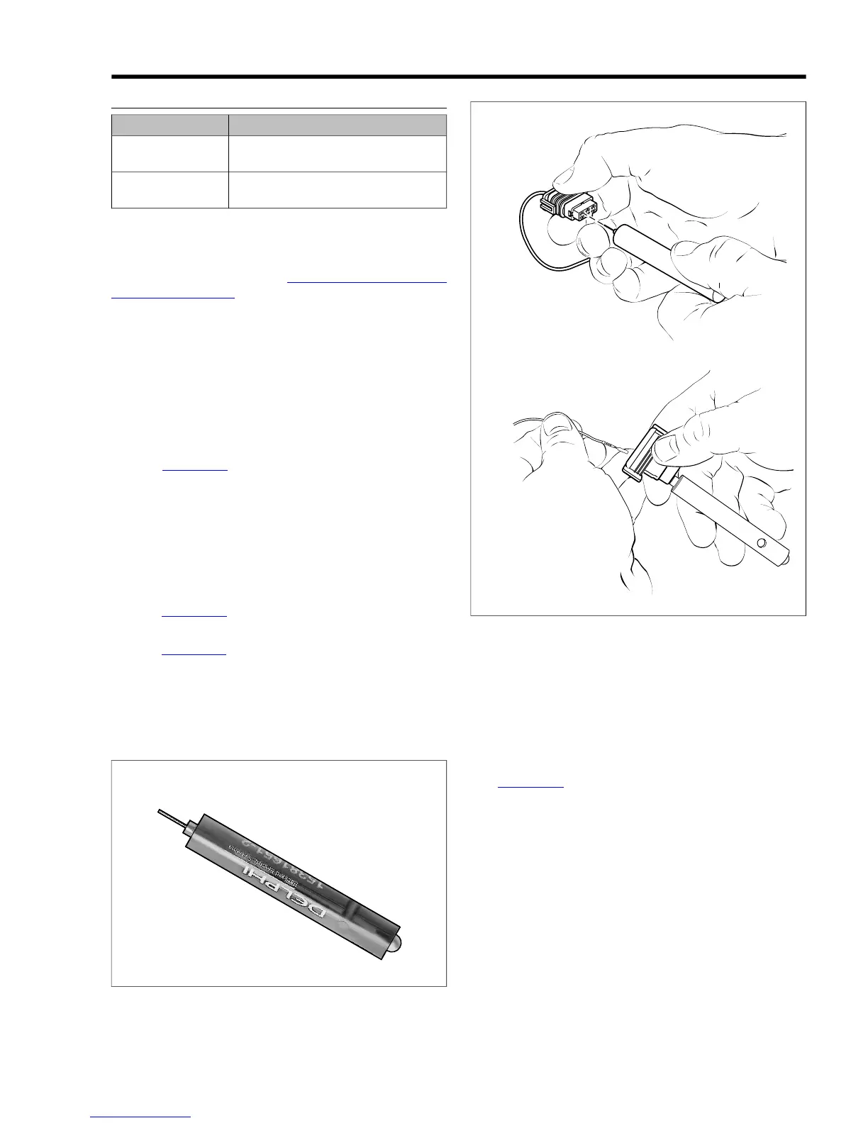
5. See Figure A-50. Push the adjacent terminals all the way
into the connector housing and then insert tool into hole
until it bottoms.
6. Leaving the tool installed, gently tug on wires to pull either
one or both terminals from wire end of connector. Remove
tool.
Figure A-50. Packard Micro 64 Connector: Insert Tool and
Remove Terminal
Installing Terminal
1. Insert terminal into its respective numbered chamber on
wire end of connector. No special orientation of the ter-
minal is necessary.
NOTE
See Figure A-51. For wire location purposes, the corners of
the socket housing are stamped (3) with the numbers 1, 6, 7
and 12, representing terminals 1-6 on one side, and 7-12 on
the other.
2. Bottom the terminal in the chamber and then gently tug
on the wire to verify that it is locked in place.
NOTE
Once the terminal is removed it may not lock in place when
first reinstalled. Until the lock engages, move the terminal back
and forth slightly while wiggling the lead.
3. Since the terminal remover tool releases two terminals
simultaneously, repeat step 2 on the adjacent terminal
even if it was not pulled from the connector housing.
2008 Dyna Service: Appendix A Connector Repair A-33



 To Next Page