4. With the center ear on the head of the secondary lockpin
facing the mating end of the connector, push secondary
lock in until head is flush with the connector housing.
Preparing Wire Leads for Crimping
Strip lead removing 1/8 in. (3.0 mm) of insulation.
Crimping Terminals
1. Inspect new socket terminal for bent or deformed contact
and crimp tails. Replace as necessary.
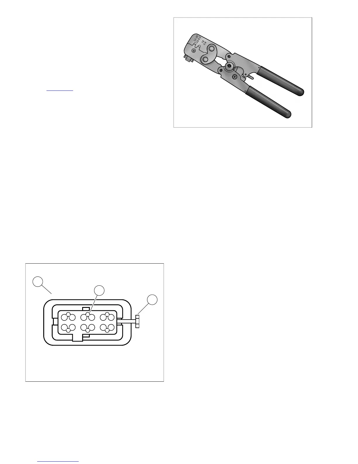
2. See Figure A-53. Squeeze the handles of the PACKARD
MICRO-64 TERMINAL CRIMPER (Part No. HD-45929)
to cycle the tool to the fully open position (1).
3. Raise locking bar and barrel holder by pushing up on
bottom tab with index finger (2).
4. With the crimp tails facing upward, insert terminal through
locking bar into front hole in barrel holder (20-22 gauge
wire) (3).
5. Release locking bar to lock position of contact. When
correctly positioned, the locking bar fits snugly in the space
at the front of the core crimp tails and the closed side of
the terminal rests on the outer nest of the crimp tool.
6. Insert wires between crimp tails until ends make contact
with locking bar.Verify that wire is positioned so that wide
pair of crimp tails squeeze bare wire strands, while the
narrow pair folds over the insulation material.
7. Squeeze handle of crimp tool until tightly closed (4). Tool
automatically opens when the crimping sequence is com-
plete.
8. Raise locking bar and barrel holder to remove contact.
Inspecting Crimps
Inspect the quality of the core and insulation crimps. Distortion
should be minimal.



 To Next Page