EasyManuals Logo

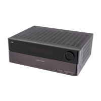
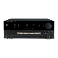
Harman Kardon AVR 2600 Service Manual

Harman Kardon AVR 2600
229 pages
To Next Page IconTo Next Page
To Previous Page IconTo Previous Page
Page #91 background imageLoading...
Page #91 background image
TMP92FD28
2007-01-30
92FD28-4
Figure 1.1 TMP92FD28 Block Diagram
( ): Initial function after reset
DVSS[8]
DVCC3A[5]
X
X2
H-OSC
Clock Gear
PLL
L-OSC
PortG
(PG0)/KI0
(PG1)/KI1
(PG2)/KI2
(PG3)/KI3
Key-on
Wake up
(PF0)TXD0
(PF1)RXD0
(PF2)SCLK0/
0CTS /CLK
/TB0OUT0
(PF3)TXD1/SPDO
(PF4)RXD1/SPDI
(PF5)SCLK1/
1CTS /SPCLK
PortF
Serial I/O
(Ch.0)
Serial I/O
(
Ch.1
)
(PC0)INT0
(PC1)INT1
(PC2)INT2/TB1IN0/TB0IN0
(PC3)INT3
PortC
16-Bit Timer
(TMRB1)
16-BitTimer
(TMRB0)
Interrupt
Controller
Mode
Controller
RESET
A
M0
A
M1
Watchdog
Timer
32-KB RAM
512-KB ROM
Program
patch logic
8-Banks
TLCS-900/H1
IX
I
Y
IZ
SP
LH
ED
CB
A
W
F
SR
32bit
PC
X
W
A
XB
C
XD
E
XH
L
Port0
D0 to D7(P00 to P07)
Port1
D8 to D15(P10 to P17)
Port4
A
0 to A7(P40 to P47)
Port5
A
8 to A15(P50 to P57)
Port6
A
16 to A23(P60 to P67)
8-Bit Timer(TMRA5)
8-Bit Timer(TMRA4)
8-Bit Timer(TMRA3)
8-Bit Timer(TMRA2)
8-Bit Timer(TMRA1)
8-Bit Timer(TMRA0)
Port8
Port7
0CS /TA1OUT(P80)
2CS (P82)
3CS / WAIT
/
TA5OUT(P83)
X1USB(P77)
USBPON(P76)
/USBOC(P75)
TA0IN/(P74)
SRLUB (P73)
SRLLB
(P72)
SRWR (P71)
RD
(
P70
)
Memory
Controller
(4-Blocks)
SPIC
RVIN [2]
RVOUT[2]
(PN1)/SDA0/TA3OUT
(PN2)/SCL0/TA2IN/SI0
(PN3)HSCLK/SCK1
(PN4)SDA1/HSSO/SO1
(PN5)SCL1/HSSI/SI1
PortN
Serial Bus I/F
(Ch.0)
HSIO
Serial Bus I/F
(
Ch.1
)
USB
D
D-
PMC
PWE
DVCC3B[1]
DVCC1A[1]
DVCC1B[1]
Regulator
Real Time
Clock
XT2
XT1
AVR3600 harman/kardon
91

Other manuals for Harman Kardon AVR 2600

Questions and Answers:

Question and Answer IconNeed help?

Do you have a question about the Harman Kardon AVR 2600 and is the answer not in the manual?

Harman Kardon AVR 2600 Specifications

General IconGeneral
BrandHarman Kardon
ModelAVR 2600
CategoryReceiver
LanguageEnglish

Related product manuals