EasyManua.ls Logo

Harman Kardon HK 980/230 User Manual

Harman Kardon HK 980/230
50 pages
To Next Page IconTo Next Page
Page #1 background imageLoading...
Page #1 background image
harman/kardon Service Manual
HK 980/230
2 x 80W STEREO AMPLIFIER
CONTENTS
TECHNICAL SPECIFICATIONS 2
REAR PANEL CONNECTIONS 3
FRONT PANEL CONTROLS 4
REMOTE CONTROL INFORMATION 5
AMP BIAS ADJUSTMENT 6
WIRING DIAGRAM 7
BLOCK DIAGRAM 8
SEMICONDUCTOR PINOUTS 9
PCB DRAWINGS 24
SCHEMATIC DIAGRAMS 32
EXPLODED VIEW AND PARTS 38
ELECTRICAL PARTS LIST 40
Released EU2008 harman/kardon, Inc. Rev 0, 11/2008
250 Crossways Park Dr.
Woodbury, New York, 11797
harman/kardon
HK 980/230 Service Manual
Page 1 of 50
Question and Answer IconNeed help?

Do you have a question about the Harman Kardon HK 980/230 and is the answer not in the manual?

Harman Kardon HK 980/230 Specifications

General IconGeneral
BrandHarman Kardon
ModelHK 980/230
CategoryAmplifier
LanguageEnglish

Summary

Technical Specifications

Connections

Connecting External Components

Describes how to connect external audio sources and devices.

Speaker Connection Guide

Details speaker cable requirements and connection methods.

External Amplifier Connection

Instructions for connecting and configuring external amplifiers.

Controls and Functions

Front Panel Control Descriptions

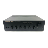
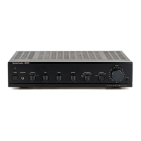
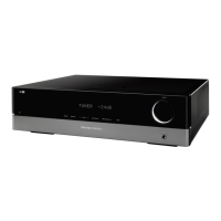
Overview and function of each control on the front panel.

Remote Control Operation

Remote Control System Operation

Explains the system remote's control capabilities.

Remote Control Usage Notes

Key considerations for using the remote control effectively.

Remote Control Operational Environment

Specifies environmental and distance factors for remote operation.

Printed Circuit Board Layouts

System Block Diagram

Detailed Circuit Schematics

Speaker Joint Board Circuit Diagram

Detailed circuit diagram for the speaker connection board.

Display System Circuit Diagram

Circuit diagram for the unit's display system.

Fuse and Power Input Schematic

Circuit diagram for the fuse and power input section.

IR Interface Circuit Diagram

Circuit diagram for the infrared remote sensor interface.

Microcontroller Unit (MCU) Schematic

Circuit diagram for the main microcontroller unit.

Main Processing Board Schematic

Circuit diagram of the central processing and signal routing board.

Exploded View and Parts Listing

Exploded Assembly View

Visual representation of component assembly and order.

Exploded View Parts Identification

Comprehensive list of parts with part numbers and quantities.

Detailed Electrical Parts List

Related product manuals