Paramete
S
ecification Unit QA Test Limits Test Conditions, Notes, and Comments
Amplifier Section
T
e
Class AB, D, other
D - - No external heat sink re
uired. Di
ital 192 kHz ternar
mode PWM.
Load Im
edance
s
eaker
4 Ohm - Minimum rated load im
edanc
Rated Out
ut Powe
200 W 200 50 H
THD
Rated Powe
<0.5 % <1 AUX-0025 + AP DSP Audio Anl
zer + 20kHz L
THD
1 Watt <0.2 % <0.4 AUX-0025 + AP DSP Audio Anl
zer + 20kHz L
DC Offse
<25 mV <35
Damping Factor >10 DF -
Measured at amplifier board, damping factor dependant on H bridge Rdson + output filter
im
edance + SMPS, t
icall
0.1 + 0.2 + 0.05 Ohm
Input Sensitivit
In
ut Reference Fre
uenc
50 Hz - L, R or LFE In
u
In
ut for 1 Watt Out
u
11.2 mVrms ±1dB RCA in
ut to s
eaker out
ut, Sin
le in
ut drive
Gain
L, R and LFE in
uts
45 dB - RCA in
ut to s
eaker out
ut, Sin
le in
ut drive
Si
nal to Nois
broad band noise from the ADC is
resent at the out
ut but not audible
SNR-A-Weighted 70 dBA 67.5
relative to 1W, AUX-0025 + AP DSP Audio Anlyzer + 20kHz LP + A-Weighting filter, PV
measured ~350 u
SNR-un-wei
hted 60 dB
- relative to 1W, AUX-0025 + AP DSP Audio Anl
zer + 20kHz LP , PV measured 2m
Residual Noise Floor <1 mVrms -
Band-pass Measurement at Line freq.+ harmonics, AUX-0025 + 22K + 20 brick wall filters,
Line level in
uts ma
be terminated usin
1K Ohm
Input Impedanc
Line In
ut 10
Ohms - A
lies to L, R or LFE In
ut
Filters & E
Im
lemented usin
DSP
Am
lifier fre
uenc
res
ons
30-300 Hz +/-1dB QA limits are relative to reference res
ons
Am
lifier fre
uenc
res
ons
20-500 Hz +/-3dB QA limits are relative to reference res
ons
LP filter ~160 Hz - Fixed, 4th orde
HP Filte
~40 Hz - Fixed, 6th orde
LF Boos
~50 Hz - Selectable, 2nd order
arametric, +3 d
AP Filte
80 Hz - Crossover
hase ali
nment.
Limite
Limiter Yes - - Di
ital limiter inte
ral to audio
rocessor IC
Maximum THD Under Limitin
5 % 7 QA tests THD at u
to 15 dB into limiter.
Features
Volume Control Ta
e
LOG - Functional
Crossover Control No - - O
tional, 3-
in header on PCBA for future models
Phase Control 0/180 De
. +/-10 2
osition, 0 & 180
LF Boost Control Yes Functional 2
osition, On & Of
LED Indicato
Yes - Functional 2 state, Blue = On, Off = Off
Tri
er In
u
Yes - Functional 3.5mm Mono Jack, Jack Sensin
ATO Control Yes - Functional 2
osition, On & Auto
Input Confi
uratio
Line In
R / L
Yes - Functional RCA Jacks, Red, White
Ri
ht and Left
LFE In Yes - Functional RCA Jack, Pur
le
Si
nal Sensin
ATO
Auto-Turn-On
es/no
Yes Functional
ATO In
ut test fre
uenc
50 Hz Functional
ATO Line in
ut level 1.5 mV Functional QA Test is 1mV verif
am
lifier is off, 2.5 mV verif
am
lifier turns on
ATO Turn-on time <1 s Functional
Time to Turn Of
15 min Functional Time is measured b
MCU, PV units measured 14 min
Ext. Tri
er inpu
Activation Voltage >3 V Functional
Designed to trigger from 3.3 - 30 V sources, AC or DC, QA test uses 3 V DC for fucntion
test. PV am
lifiers measured 2.9 V AC, 1.6 V DC.
Activation curren
<3 mA Functional ~30k in
ut im
edance
Transients/Pop
ATO Transient <0.5 V-
Functional S
eaker Out
ut, Am
lifier wake from standb
, PV sam
le < 0.1 V, not audibl
Turn-on Transien
<0.5 V-
Functional AC Line Connect, PV sam
le < 0.1 V, not audibl
Turn-off Transien
<0.5 V-
Functional AC Line Disconnect, PV sam
le < 0.1 V, not audibl
Protections
Out
ut Short Circuit Protection Yes - - Direct short between out
ut terminal, recoverable
1 W, 50 H
Out
ut Over Current
rotectio
12 A - Inte
ral to
ower I
Output DC Protection Yes - -
Detects shorts to ground or VCC on outputs (H-Bridge Failure), LED blinks rapidly, SMPS is
shut down to
revent, checks and attem
ts recover
ever
20 seconds
Thermal Protection Yes NTC sensor ad
acent
ower am
lifier IC
Mains Fuse Ratin
120v
6.3 A slo-blo 250V, Internal Fuse, SMPS PCBA mounted
i
tail, soldered in
lace
Mains Fuse Ratin
230v
5 A slo-blo 250V, Internal Fuse, SMPS PCBA mounted
i
tail, soldered in
lace
Efficienc
Efficienc
at rated
owe
75 % -
Efficienc
at 1/8 of rated
owe
60 % -
Standb
In
ut
owe
0.8 W <1
Idle in
ut
owe
8 W <10
Nominal Line voltage, Mains input to speaker outputs.
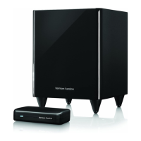
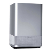
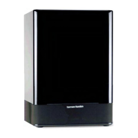
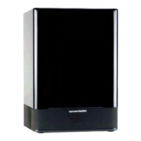
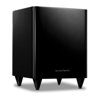
HKTS200SUB Amplifier Specifications
HKTS200SUB harman/kardon
 Loading...