7
160S
lue seriesb
160S
160S
160S
controls controls
160S
notes notes
160S
160S
160S
Operations
160S
160S
160S
160S
160S
160S
160S
160S
160S
160S
160S
160S
160S
160S
160S
Operations
Inspection Inspection
Operating Operating
Operating Operating
Connection
Connection
Installation
Installation
Technical
Technical
Introduction Introduction
to your system
to your system
considerations
considerations
contents
contents
concept
concept
diagram
diagram
applications
applications
support and factory service
support and factory service
160S
Specifications
Specifications
160S
160S
160S
160S
160S
160S
Manual
Manual
Design
Design
Block
Block
Controls
Controls
Advanced
Advanced
Warranty
Warranty
lue seriesb
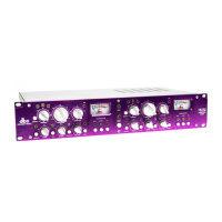
Connections
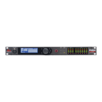
The 160SL is connected for operation using the rear panel XLR connectors. Note that the two rear panel input
sections have a push-switch which lifts the contact on pin #1 (ground). Keep this switch in the OFF position (pin
#1 connected) until all connections are made. Be sure that your input and output cables are wired in the “pin
2-hot” configuration, which is printed on the rear panel of the 160SL. For more information on other types of
connections, refer to the section entitled Operating Notes.
When connecting the 160SL, refer to the following steps:
• Turn OFF all equipment BEFORE making any connections.
• Mount the 160SL in a 2U rack space. (Optional)
The 160SL requires a two rack-space height and a standard 19 inch rack-space width. It can be
mounted above or below anything that doesn’t create excessive heat, since it requires no special
ventilation. Ambient temperatures should not exceed 113°F (45°C) when equipment
is powered.
Caution: Never remove the cover. There are no user serviceable parts inside.
• Make connections via XLR connectors.
• Plug in AC power cable and power ON the unit.
Note: Check the line voltage printed on the rear panel of the 160SL and verify that it is correct for your area.
Two Basic Compressor Setups:
A: Channel One shows processing of a group
or aux main output. Signal goes to the 160SL
input from the output/insert send of the
console, and returns to the console via the
input/insert return of the same group/aux
on the console.
B: Channel Two shows connections for
processing a signal from a single channel.
Input of the 160SL is fed by the channel insert
output/send, and returns to the console via
the insert input/return.
Operating Level
Headroom
Clipping
Noise Floor
Useable dynamic range
Clipped signal heavily distorted
Audio levels below here are not heard, because of noise
+10
0
-10
-20
time
+10
0
-10
-20
time
input
dBu
Figure 2 Figure 1
Figure 3 Figure 4
input
dBu
+10
0
-10
-20
time
+10
0
-10
-20
time
output
dBu
output
dBu
INPUT OUTPUT INPUT OUTPUT
CHANNEL ONECHANNEL TWO
AB
2
1
3
Jensen®
Output
Transformer
Jensen
®
Output
Transformer
10k 1W
GND
Switch
GND
Switch
BALANCED FLOATING OPERATION UNBALANCED FLOATING OPERATION
Chassis
Ground
Chassis
Ground
Chassis
Ground
Ground Switch open
Unbalance Switch open
Ground Switch open
Unbalanced Switch closed
(6dB drop in output level)
Jensen®
Output
Transformer
Jensen
®
Output
Transformer
10k 1W
GND
Switch
GND
Switch
BALANCED GROUND-
REFERENCED OPERATION
UNBALANCED GROUND-
REFERENCED OPERATION
Chassis
Ground
Chassis
Ground
Ground Switch closed
Unbalance Switch open
Ground Switch closed
Unbalance Switch closed
(6dB drop in output level)
+
-
+
-
+
-
+
-
Source
Device
(mixer)
EQ
IN
OUT
Audio
Outputs
Source
Device
(mixer)
Audio
Outputs
DELAY
Audio
Inputs
Audio
Outputs
Sidechain
Return
Sidechain
Send
Audio
Inputs
Audio
Outputs
Sidechain
Return
Sidechain
Send
2
1
3
Chassis
Ground
2
1
3
Chassis
Ground
2
1
3
Chassis
Ground
160SL
160SL
UL60065
FUSE:
T 500mA L
250V
160SL
160SL
160SL
controls controls
160SL
notes notes
160SL
160SL
160SL
Operations
160SL
160SL
160SL
160SL
160SL
160SL
160SL
160SL
160SL
160SL
160SL
160SL
160SL
160SL
Operations
Inspection Inspection
Operating Operating
Operating Operating
Connection
Connection
Installation
Installation
Technical
Technical
Introduction Introduction
to your system
to your system
considerations
considerations
contents
contents
concept
concept
diagram
diagram
applications
applications
support and factory service
support and factory service
160SL
Specifications
Specifications
160SL
160SL
160SL
160SL
160SL
160SL
Manual
Manual
Design
Design
Block
Block
Controls
Controls
Advanced
Advanced
Warranty
Warranty
 Loading...