13
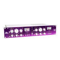
160S
lue seriesb
160S
160S
160S
controls controls
160S
notes notes
160S
160S
160S
Operations
160S
160S
160S
160S
160S
160S
160S
160S
160S
160S
160S
160S
160S
160S
160S
Operations
Inspection Inspection
Operating Operating
Operating Operating
Connection
Connection
Installation
Installation
Technical
Technical
Introduction Introduction
to your system
to your system
considerations
considerations
contents
contents
concept
concept
diagram
diagram
applications
applications
support and factory service
support and factory service
160S
Specifications
Specifications
160S
160S
160S
160S
160S
160S
Manual
Manual
Design
Design
Block
Block
Controls
Controls
Advanced
Advanced
Warranty
Warranty
lue seriesb
UL60065
FUSE:
T 500mA L
250V
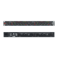
Rear Panel
Au dio Input and Output Connectors: Each audio input connector on the rear panel of the 160SL
is a gold-plated Neutrik
®
XLR female connector. The no-compromise approach to the 160SL required
that we use gold-plated connectors, due to their high conductivity and low EMI/RFI susceptibility. The
connectors are default wired in balanced mode (pin 2 hot, AES convention), although supplying an
unbalanced signal presents no difficulty to the 160SL.
Pin 1 Lift Switch: Associated with each input connector is a switch labeled Pin 1 Lift. Depressing
this switch lifts pin 1 of the input XLR from all ground references. This may be necessary to break a
troublesome ground loop which is causing hum in the system.
Un balance Switch: The Unbalance switch is associated only with the Output connectors of the 160SL.
When it is in the IN position, the output of the 160SL is switched from balanced to unbalanced. (See
wiring diagram below.) In the OUT position, the 160SL’s outputs are balanced in the “pin 2 hot”
configuration. Note that when the output is unbalanced via the switch, there is a 6dB drop in output
signal level. If you do not wish to experience the 6dB drop in output signal level, you may short pin 3
of the output cable to ground, rather than using the Unbalance switch.
Operating Level
Headroom
Clipping
Noise Floor
Useable dynamic range
Clipped signal heavily distorted
Audio levels below here are not heard, because of noise
+10
0
-10
-20
time
+10
0
-10
-20
time
input
dBu
Figure 2 Figure 1
Figure 3 Figure 4
input
dBu
+10
0
-10
-20
time
+10
0
-10
-20
time
output
dBu
output
dBu
INPUT OUTPUT INPUT OUTPUT
CHANNEL ONECHANNEL TWO
AB
2
1
3
Jensen®
Output
Transformer
Jensen
®
Output
Transformer
10k 1W
GND
Switch
GND
Switch
BALANCED FLOATING OPERATION UNBALANCED FLOATING OPERATION
Chassis
Ground
Chassis
Ground
Chassis
Ground
Ground Switch open
Unbalance Switch open
Ground Switch open
Unbalanced Switch closed
(6dB drop in output level)
Jensen®
Output
Transformer
Jensen
®
Output
Transformer
10k 1W
GND
Switch
GND
Switch
BALANCED GROUND-
REFERENCED OPERATION
UNBALANCED GROUND-
REFERENCED OPERATION
Chassis
Ground
Chassis
Ground
Ground Switch closed
Unbalance Switch open
Ground Switch closed
Unbalance Switch closed
(6dB drop in output level)
+
-
+
-
+
-
+
-
Source
Device
(mixer)
EQ
IN
OUT
Audio
Outputs
Source
Device
(mixer)
Audio
Outputs
DELAY
Audio
Inputs
Audio
Outputs
Sidechain
Return
Sidechain
Send
Audio
Inputs
Audio
Outputs
Sidechain
Return
Sidechain
Send
2
1
3
Chassis
Ground
2
1
3
Chassis
Ground
2
1
3
Chassis
Ground
160SL
160SL
UL60065
FUSE:
T 500mA L
250V
Gr ound Switch: The Ground switch, when in the IN position, references the center tap of the output
transformer to the chassis ground. This ensures that the signal from the 160SL, regardless of previous
grounding systems earlier in the audio chain, can deliver a chassis-grounded output signal free of hum
and interference to the output connector. The combination of the three switches associated with the
audio input/output connectors ensures that the 160SL is versatile enough to interface with any equipment
and can deliver clean audio to the output, free of hum and interference. (See the following diagram for
details of the Ground switch operation.)
controls
160SL
notes notes
160SL
160SL
160SL
Operations
160SL
160SL
160SL
160SL
160SL
160SL
160SL
160SL
160SL
160SL
160SL
160SL
160SL
160SL
Operations
Inspection Inspection
Operating
Operating
Operating Operating
Connection
Connection
Installation
Installation
Technical
Technical
Introduction Introduction
to your system
to your system
considerations
considerations
contents
contents
concept
concept
diagram
diagram
applications
applications
support and factory service
support and factory service
160SL
Specifications
Specifications
160SL
160SL
160SL
160SL
160SL
160SL
Manual
Manual
Design
Design
Block
Block
Controls
Controls
Advanced
Advanced
Warranty
Warranty
 Loading...