13
Chapter 1 Overview of the FHA-C series
Tor sion
A
O
B
Torque
O
A
-T
Hysteresis
Loss
+
0
1
1
0
T
Tor sion
Torque
0
0
K
K
T
T
1
1
1
2
2
2
3
K
O
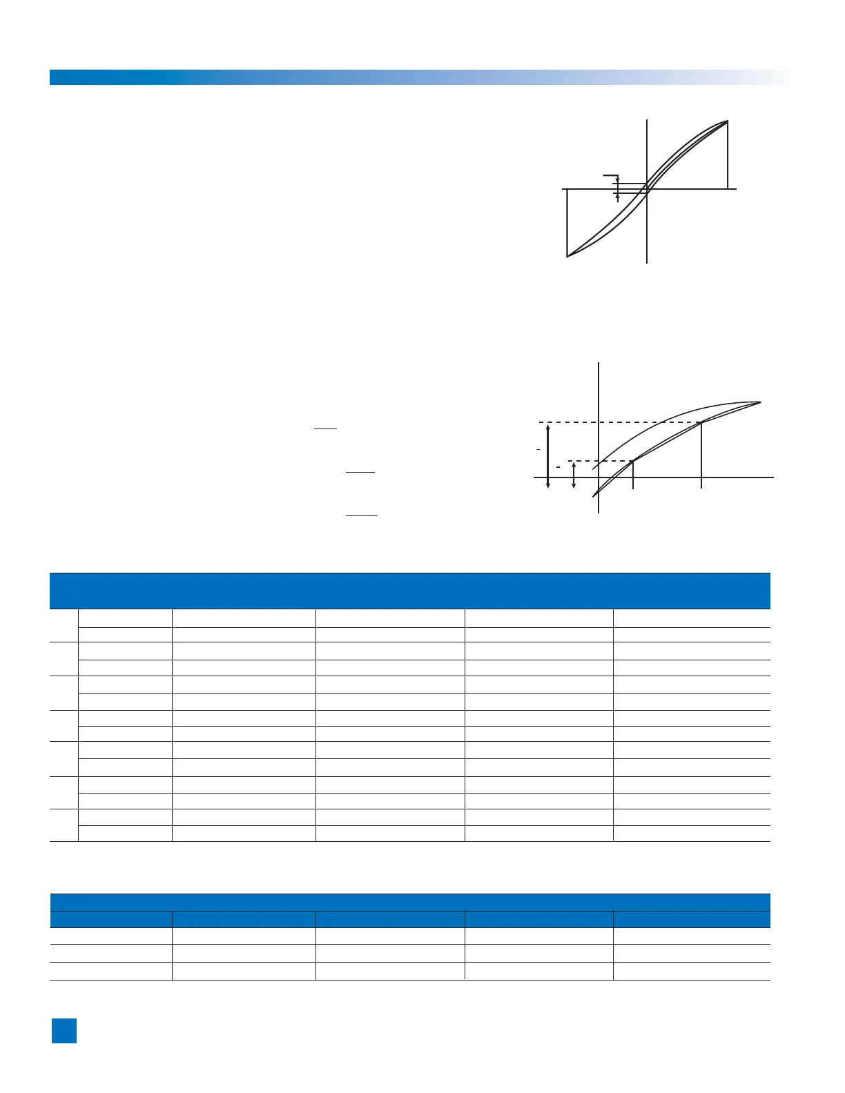
1-9-2 Torsional Stiffness
When a torque is applied to the output flange of the actuator with the motor locked,
the resulting torsional wind up is near proportional to the torque.
The upper right figure shows the torsional stiffness characteristics of the output flange
applying torque starting from zero to plus side [+T
0] and minus side [–T0].
This trajectory is called torque-torsion characteristics which typically follows
a loop 0→A→B→A’→B’→A as illustrated. The torsional stiffness of the
FHA-C actuator is expressed by the slope of the curve that is a spring rate
(wind-up) (N
•m/rad).
The torsional stiffness may be evaluated by dividing torque-torsion characteristics
curve into three major regions. The spring rate of each region is expressed
K
1, K2, and K3 respectively.
K
1: spring rate for torque region 0-T1
K2: spring rate for torque region T1-T2
K3: spring rate for torque region over T2
The wind-up for each region is expressed as follows:
T
•
Wind-up for torque region 0-T1:
ϕ
=
K
1
T - T
1
•
Wind-up for torque region T1-T2:
ϕ
=
θ
1 +
K
2
T - T
2
•
Wind-up for torque region over T2:
ϕ
=
θ
2 +
K
3
Ø
ϕ
: Wind-up
The table below shows T
1-T3, K1-K3, and
θ
1-
θ
2 values of each actuator.
Model FHA-17C FHA-25C FHA-32C FHA-40C
Reduction Ratio
1:50 1:100 1:160 1:50 1:100 1:160 1:50 1:100 1:160 1:50 1:100 1:160
T1 N•m 7.0 7.0 7.0 29 29 29 54 54 54 108 108 108
kgf
•m 0.7 0.7 0.7 3.0 3.0 3.0 5.5 5.5 5.5 11 11 11
K
1 x10
4
N•m/rad 1.1 1.3 1.3 4.7 6.1 6.1 8.8 11 11 17 21 21
kgf
•m/arc min 0.32 0.4 0.4 1.4 1.8 1.8 2.8 3.2 3.2 5.0 6.3 6.3
θ
1 x10
-4
rad 6.4 5.1 5.1 6.2 4.8 4.8 6.1 4.9 4.9 6.4 5.1 5.1
arc min 2.2 1.8 1.8 2.1 1.7 1.7 2.1 1.7 1.7 2.2 1.8 1.8
T
2 N•m 25 25 25 108 108 108 196 196 196 382 382 382
kgf
•m 2.5 2.5 2.5 11 11 11 20 20 20 39 39 39
K
2 K2x10
4
N•m/rad 1.3 1.7 1.7 6.1 7.7 7.7 11 14 14 21 29 29
kgf
•m/arc min 0.4 0.5 0.5 1.8 2.3 2.3 3.4 4.2 4.2 6.3 8.5 8.5
θ
2 x10
-4
rad 19.5 15.6 15.6 19.2 15 15 19.1 15.1 15.1 19.3 14.7 14.7
arc min 6.7 5.4 5.4 6.6 5.1 5.1 6.4 5.2 5.2 6.6 5.0 5.0
K
3 x10
4
N•m/rad 2.0 2.5 2.5 8.4 11 11 15 20 20 30 37 37
kgf
•m/arc min 0.6 0.75 0.75 2.5 3.3 3.3 4.5 5.8 5.8 9 11 11
The table below shows torque-wind-up relation for reference.
(unit:N
•m)
Model
FHA-17C FHA-25C FHA-32C FHA-40C
Reduction Ratio
1:50 1:100 1:160 1:50 1:100 1:160 1:50 1:100 1:160 1:50 1:100 1:160
2 arc-min 6.3 8.1 8.1 27 37 37 51 63 63 98 129 129
4 arc-min 14 18 18 62 82 82 117 148 148 220 300 300
6 arc-min 22 29 29 97 136 136 179 243 243 340 490 490
 Loading...