CONTENTS
Safety Guide
1
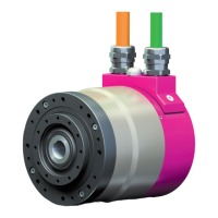
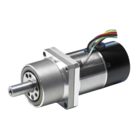
Chapter 1 Overview of the FHA-C series 3
1-1 Features
3
1-2 Ordering information 4
1-3 Combinations with drivers 4
1-4 Specifications of FHA-C actuators 5
1-4-1 For incremental positioning system 5
1-4-2 For absolute positioning system 6
1-5 External dimensions of FHA-C actuators 7
1-5-1 For incremental positioning system 7
1-5-2 For absolute positioning system 9
1-6 Mechanical accuracy of FHA-C actuators 11
1-7 One-way positioning accuracy 12
1-8 Encoder resolution 12
1-9 Torsional Stiffness of actuators 12
1-9-1 Moment stiffness 12
1-9-2 Torsional stiffness 13
1-10 Rotary direction 14
1-11 Impact resistance 14
1-12 Vibration resistance 14
1-13 Torque-speed characteristics 14
1-14 Cable specifications 17
1-15 Signal Waveforms 18
Chapter 2 Selection Guidelines 19
2-1 Allowable load inertia 19
2-2 Variable load inertia 19
2-3 Verifying loads 20
2-4 Duty cycles 24
2-4-1 Actuator speed 24
2-4-2 Load inertia 24
2-4-3 Load torque 24
2-4-4 Acceleration time and deceleration time 25
2-4-5 Calculating equivalent duty 26
2-4-6 Effective torque and average speed 29
2-4-7 Permissible overloaded time 30
2-4-8 Regeneration energy 30
Chapter 3 Installing the FHA actuator 31
3-1 Receiving Inspection 31
3-2 Notice on handling 32
3-3 Location and installation 32
3-3-1 Environment of location 32
3-3-2 Installation 33
Chapter 4 Options 34
4-1 AC100V power supply 34
4-2 Brake for motor 35
4-2-1 Specifications for incremental encoder system 35
4-2-2 Brake leads 35
4-3 Cable-end connectors 36
4-4 Clamp for output 36
4-5 5 meter cables 37
4-6 Cable outlets from back face 37
4-7 Rotary position sensor set 38
4-7-1 Specifications 38
4-7-2 Adjusting procedure for sensor locations 39
4-7-3 Movable range for each limit switch 40
4-8 Extension cables 41
4-9 Connectors 41
Appendix 1 Unit conversion 42
Appendix 2 Moment of inertia/Calculation of mass and moment of inertia 44
2 Inertia of cylinder 46
Warranty and terms 47
FHA-C series AC Servo Actuator Manual
 Loading...