19
2
2
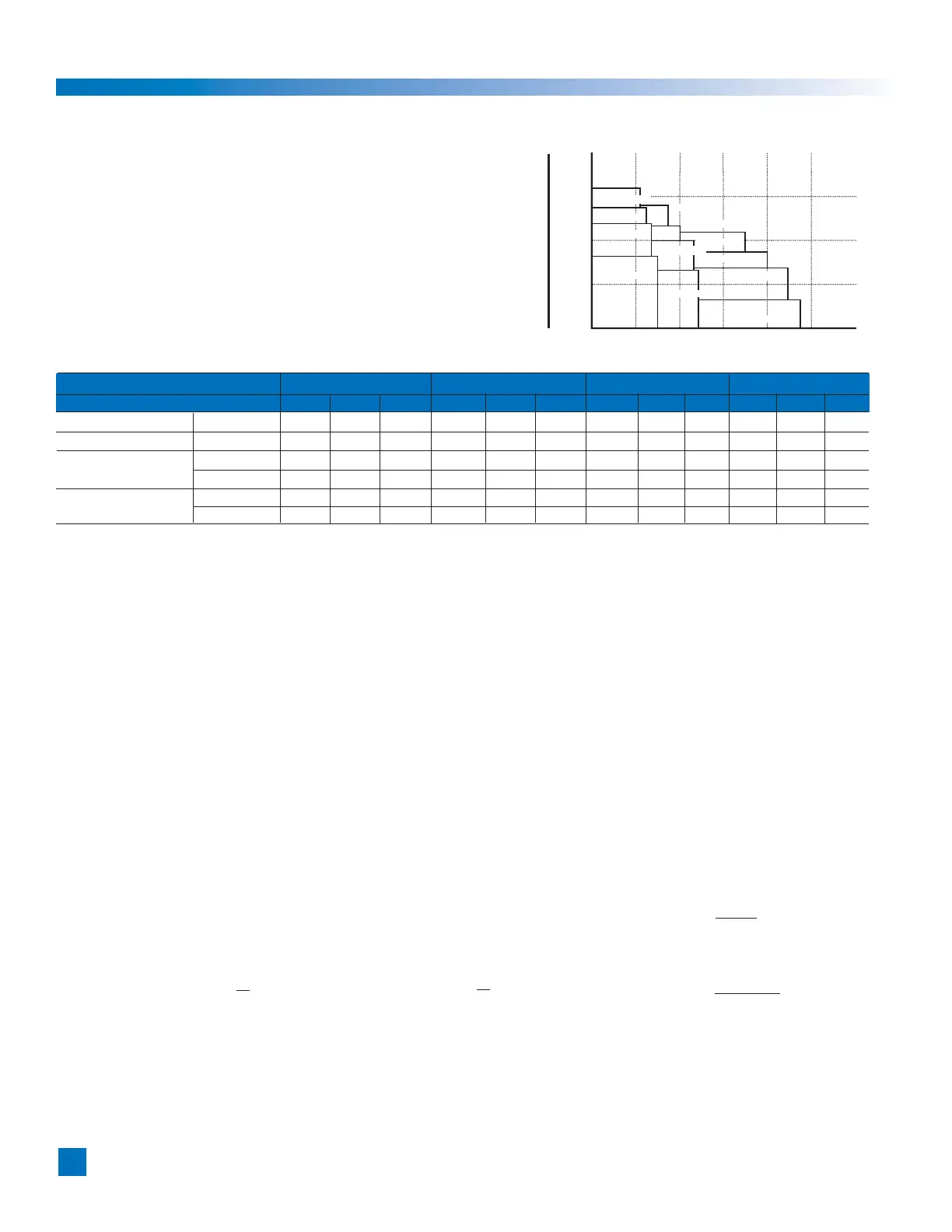
Inertia
(kg
•
m
) (kgf
•
cm
•
s
)
1000 10000
100 1000
10 100
1 10
0.1 1
0 20 40 60 80 100 120
Max. speed (r/min)
FHA-40C-160
FHA-40C-100
FHA-32C-160
FHA-32C-100
FHA-25C-160
FHA-40C-50
FHA-25C-100
FHA-32C-50
FHA-17C-160 FHA-25C-50
FHA-17C-100
FHA-17C-50
Chapter 2 Selection guidelines
2-1 Allowable load inertia
To achieve high accuracy performance, select an
FHA actuator wherein the allowable moment of inertia
(reference value) is greater than the load inertia.
Refer to appendix 1 for the calculation of moment inertia.
When selecting the actuator make certain that the load
inertia and the maximum speed are less than the allowable
values that are indicated in the table below.
Actuator model FHA-17C FHA-25C FHA-32C FHA-40C
50 100 160 50 100 160 50 100 160 50 100 160
Reduction ratio 1:50 1:100 1:160 1:50 1:100 1:60 1:50 1:100 1:160 1:50 1:100 1:160
Maximum speed (r/min) 96 48 30 90 45 28 80 40 25 70 35 22
Moment of inertia kg
•m
2
0.17 0.67 1.7 0.81 3.2 8.3 1.8 7.1 18.1 4.9 19.5 50
of actuator kgf
•cm•s
2
1.7 6.9 17 8.3 33 85 18 72 185 50 200 510
Allowable moment kg
•m
2
0.54 2.1 5.1 2.4 10 25 5.4 21 54 15 60 150
of inertia kgf
•cm•s
2
5.4 21 52 24 100 260 55 210 550 150 610 1500
2-2 Variable load inertia
FHA-C series actuators include Harmonic Drive
®
gearing that has a high
reduction ratio. Because of this there are minimal effects of variable
load inertias to the servo drive system. In comparison to direct servo
systems this benefit will drive the load with a better servo response.
For example, assume that the load inertia increases to N-times during
its motion (for example, robot arms). The effect of the variable load
inertia to the [total inertia converted into motor shaft] is as follows:
The symbols in the formulas are:
J
S
: Total inertia converted into motor shaft
J
M
: Moment inertia of motor
R: Reduction ratio of FHA actuator
L: Ratio of load inertia to motor inertia
N: Variation ratio of load inertia
• Direct drive
Before: J
S
= JM ( 1 + L ) After: Js’ = JM ( 1+ NL )
Ratio: Js’/Js =
1 + NL
1 + L
• FHA actuator drive
Before: Js = J
M
(
1+
L
)
After: Js’ = J
M
(
1 +
NL
)
Ratio: Js’/Js =
1 + NL / R2
R2
R2
1 + L / R2
In the case of the FHA actuator drive, as the reduction ratio is [R=50], [R=100] or [R160] and the square of the reduction ratio
[R
2
=2500], [R
2
=10000] or [R
2
=25600] the denominator and the numerator of the ratio are almost [1]. Then the ratio is [F=1].
This means that FHA drive systems are hardly effected by the load inertia variation. Therefore, it is not necessary
to take the load inertia variation into consideration for selecting an FHA actuator or for setting up the HA-675 or HA-655 driver.
Chapter 2 Guidelines for sizing
 Loading...