Chapter 3 Installing the HLP 4800 Platform Connecting the Alarm Relay
© 2009 Harmonic Inc. 16 HLP 4800, Version 1.0, Rev A
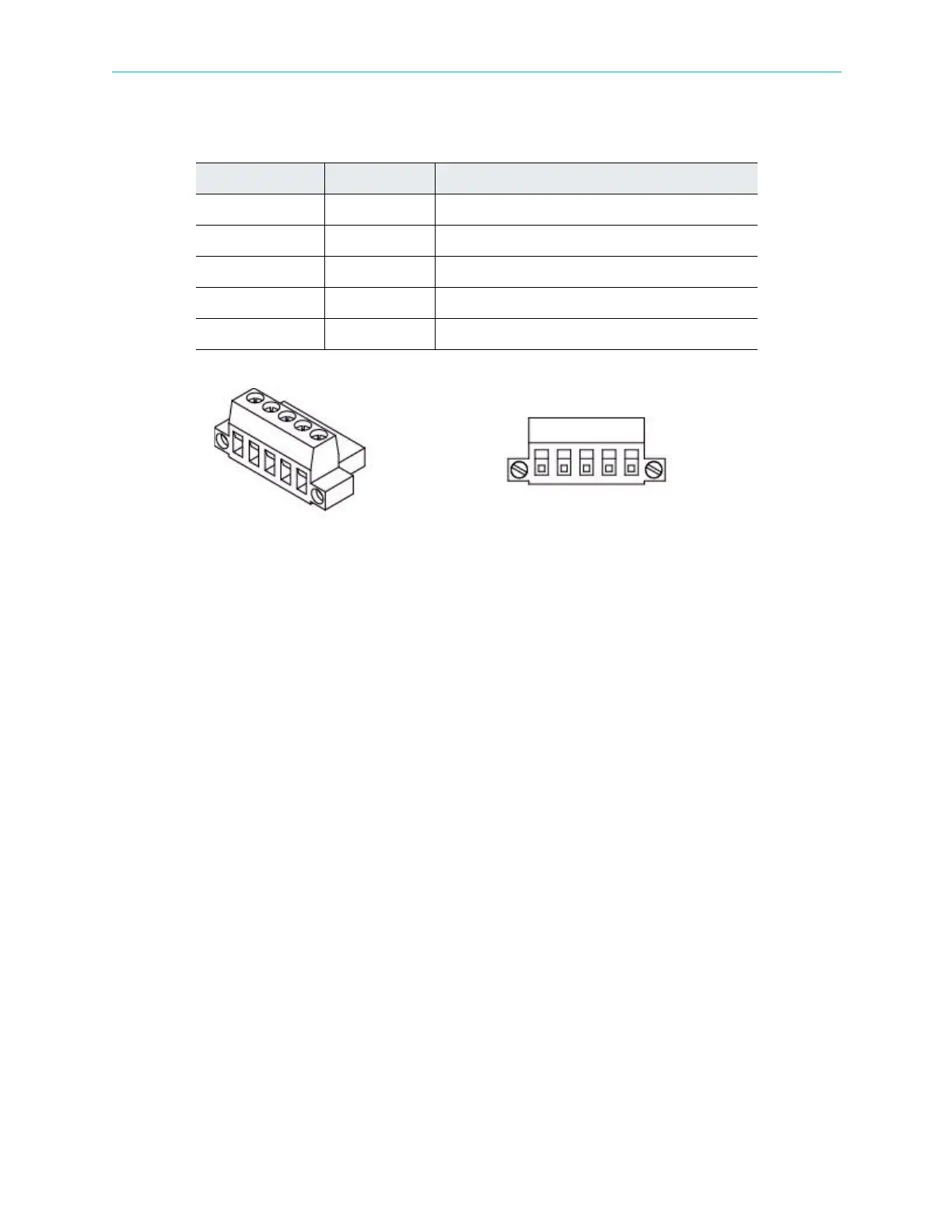
Table 3-1: Alarm Relay Pins on page 16 shows the pin definitions.
Figure 3-2: Alarm relay terminal block Harmonic part number 406-0000560
When operating normally with no alarm present, Pin 1 and Pin 2 are open, while Pin 3 and Pin
5 are closed.
When an alarm occurs, Pin1 and Pin 2 make electrical contact, while Pin 3 and Pin 5 are left
open. This remains until the alarm condition is removed.
Table 3-1: Alarm Relay Pins
Pin Label Function
Pin 1 NO Normally open
Pin 2 NO1 Normally open 1
Pin 3 NC Normally closed
Pin 4 GND Ground
Pin 5 NC1 Normally closed 1
 Loading...