13. Once the desired pipeline pressure has been achieved, re- assemble the front cover using a Phillips Head Screwdriver.
14. Non-ammable gas systems will come with a power supply and integral alarm. Plug the power supply cable into the bottom connector on the control box and the other end into a
120VAC electrical outlet. The status lights on the front of the box should be green (NORMAL) on both sides. When the primary side is depleted, the system will change over to the
reserve or secondary side and the primary side light will go from green (NORMAL) to red (EMPTY).
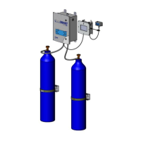
10. Cylinder Changeout
When the primary side or bank of cylinders has been depleted, the alarm system will indicate this by changing the lights on the primary side from green (NORMAL) to red (EMPTY).
The empty cylinders can then be removed and new (full) cylinders put in their place. Once the new (full) cylinders are put in place, it is recommended that the primary knob be
turned 180 degrees to point away from the new (full) cylinders. This will insure a “First In-First Out” cylinder rotation where uninterrupted gas supply can be achieved.
11. Optional Remote Alarms
Optional Remote Audio/Visual Alarms are available for all systems (see Table 1). Remote alarms for non-ammable gas systems have optional 10 ft. or 50 ft. cable lengths.
Flammable gas alarms do not come with cable/wiring.
Part Number Gas Service Description
4300698 Non-Flammable Alarm Box Only
4300699 Non-Flammable 10’ Cable
4300709 Non-Flammable 50’ Cable
4300343 Acetylene Remote Alarm Kit
4300344 Hydrogen Remote Alarm Kit
4300345 LPG Remote Alarm Kit
Table 1
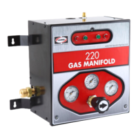
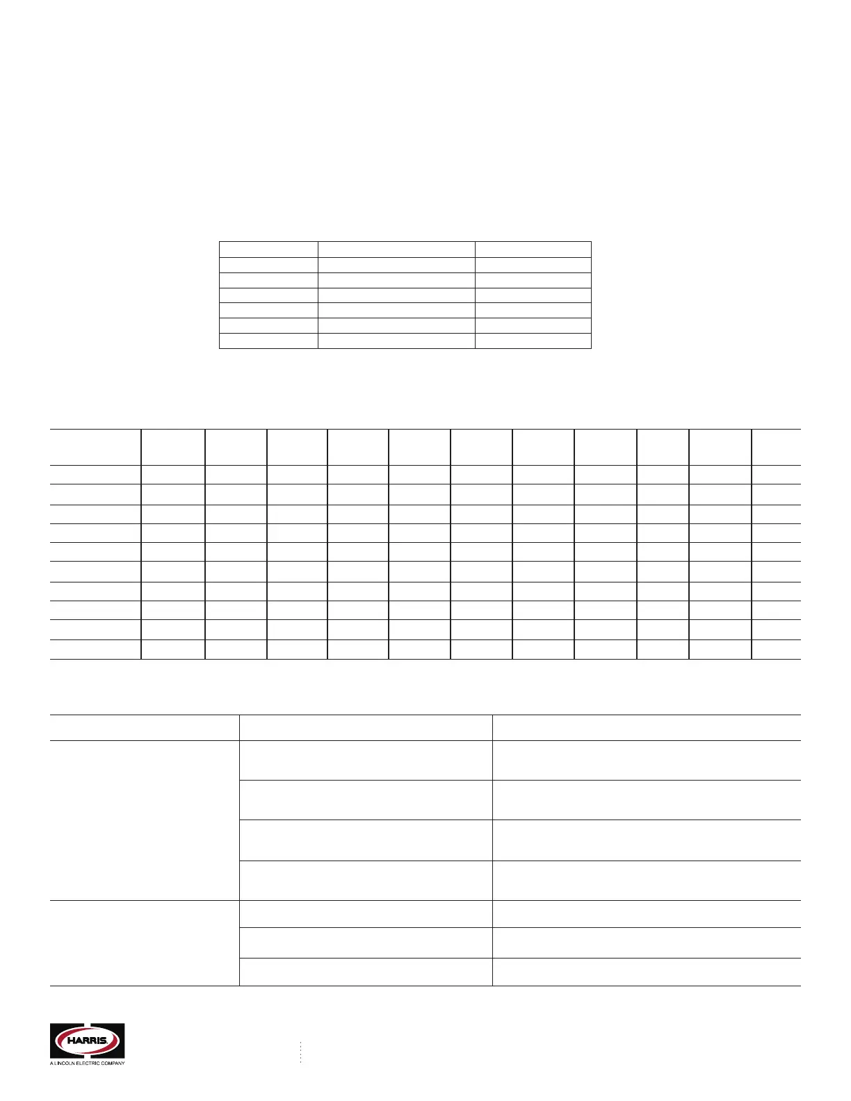
12. Replacement Parts
The following chart (Table 2) contains a listing of common replacement parts available for the Model 220 Series Switchover Manfold Systems. Other replacement parts are available.
Contact the Harris Products Group for additional information.
Model Control Primary Preset Outlet Inlet Delivery Pressure Green Red Heater Power
Number Box P/N Regulator Regulator Regulator Gauge Gauge Switch Light Light Assembly Supply
220 Oxy/Inlet 4301529 3001570 3001602 3001612 9006838-2 9006842 4300684 4300688 4300687 N/A 9005489
220 Acet 4301530 3001568 3001600 3001610 9006841 9006844 N/A N/A N/A N/A N/A
220 Flammable 4301531 3001570 3001602 3001612 9006838-2 9006842 N/A N/A N/A N/A N/A
220 LPG 4301532 3001569 3001601 3001611 9006841 9006843 N/A N/A N/A N/A N/A
220 HL 4301533 3001570 3001602 3001612 9006838-2 9006842 4300684 4300688 4300687 9005421 9005489
220 HP 4301535 3001571 3001603 3001613 9006838-3 9006842 4300684 4300688 4300687 N/A 9005489
220 HPHL 4301534 3001571 3001603 3001613 9006838-4 9006842 4300684 4300688 4300687 9005421 9005489
220 HP Flammable 4301536 3001571 3001603 3001613 9006838-5 9006842 N/A N/A N/A N/A N/A
240 4301537 3001572 3001605 3001609 9006841-2 9006842 4300686 4300688 4300687 N/A 9005489
240 HP 4301538 3001573 3001604 3001608 9006840-2 9006841 4300685 4300688 4300687 N/A 9005489
Table 2
13. Troubleshooting
The following troubleshooting guide addresses some of the common failure modes and possible solutions.
PROBLEM PROBABLE CAUSE REMEDY OR CHECK
Leakage at manifold header connection Check for leaks at all joints and connections; Retighten, repair
or replace headers or ttings.
Loss of Cylinder Contents Leakage in downstream piping system Check for leaks at all joints and connections; Retighten, repair
or replace piping or ttings.
Leakage at cylinder valve Check for leaks at cylinder connection and valve; Replace
cylinder
Regulator leaks Check for leaks at regulator connections; Replace connections
and/or regulator
Line regulator setting too high Set delivery pressure to specications
Venting at relief valve Overpressure due to creeping or faulty regulator Replace regulator
Regulator freeze-up (Nitrous oxide or carbon dioxide) Reduce the ow demand or increase the number of supply cylinders.
THE HARRIS PRODUCTS GROUP
www.harrisproductsgroup.com
1.800.241.0804
 Loading...