www.SteamPoweredRadio.Com
HT
250FM
HT
500FM
THE-1
EXCITER
APC
PA
LOW
PASS
FILTER
CONTROLLER
ANT
COMMAND
&
STATUS
2303-023
ANT
HT
1FM
ONLY
THE-1
EXCITER
SPLITTER
COMBINER
LOW
PASS
FILTER
APC
CONTROLLER
'-------------l
-----------
COMMAND
&
STATUS
connection to the antenna and located at the
output
of
the lowpass filter.
SWR
is a ratio reading (example 1.15:1)
on
the POWER meter.
APC voltage is a relative indication
of
the
functioning
of
the automatic power control
and VSWR foldback loop. It is provided to
facilitate setup of the transmitter APC loop.
BAIT
TEST: Checks voltage
of
the op-
tional 9-Volt Controller battery which is
used for long term retention
of
the control
settings.
A
push-to-test pushbutton switch
eliminates the possibility
of
leaving the
MULTIMETER in this test position and
draining the battery.
NOTE
The control settings
(TX ON-TX
OFF
state
and
power level setting) are backed
up
for at least five hours during power
outages by a capacitive storage device.
If
longer outages are anticipated, a bat-
tery may be installed.
N
OTE
The 9-Volt battery used
is
a common va-
riety
transistor
radio
battery
(DO
NOT
USE
ALKALINE
BATTERY)
.
In
normal
operation,
the
battery
has
no
drain
on
it
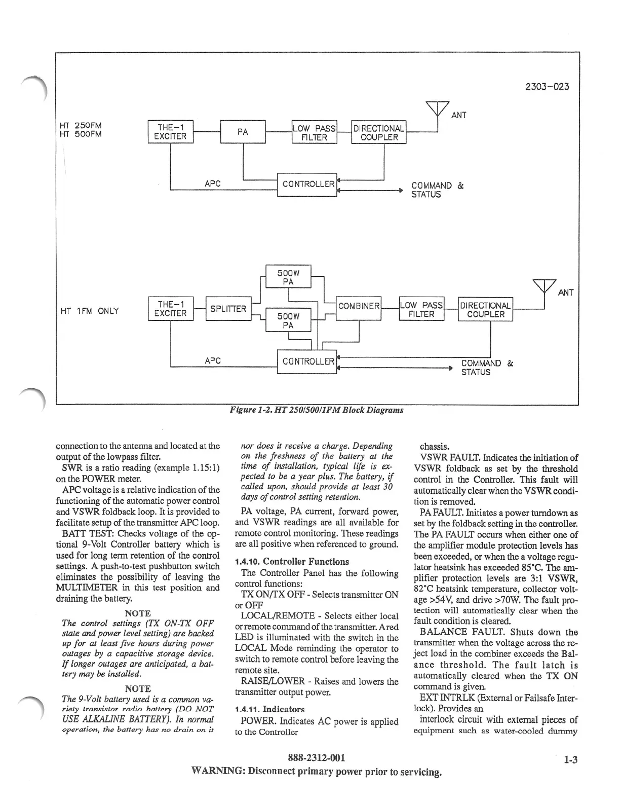
Figure 1-2. HT 250/500/lFM Block Diagrams
nor does it receive a charge. Depending
on the freshness
of
the battery at the
time
of
installation, typical life
is
ex-
pected to be a year plus. The battery,
if
called upon, should provide at least
30
days
of
control setting retention.
PA
voltage,
PA
current, forward power,
and VSWR readings are all available for
remote control monitoring. These readings
are all positive when referenced to ground.
1.4.10.
Controller Functions
The Controller Panel has the following
control functions:
TX
ON/TX
OFF - Selects transmitter ON
or OFF
LOCAL/REMOTE - Selects either local
or remote command
of
the transmitter. A red
LED is illuminated with the switch in the
LOCAL Mode reminding the operator
to
switch to remote control before leaving the
remote site.
RAISE/LOWER - Raises and lowers the
transmitter output power.
1.4.11.
Indicators
POWER. Indicates
AC
power is applied
to
the
Controller
888-2312-001
chassis.
VSWR
FAULT.
Indicates the initiation
of
VSWR foldback
as
set by the threshold
control in the Controller. This fault will
automatically clear when the VSWR condi-
tion is removed.
PA
FAULT.
Initiates a power tumdown as
set by the foldback setting in the controller.
The
PA
FAULT occurs when either one
of
the amplifier module protection levels has
been exceeded, or when the a voltage regu-
lator heatsink has exceeded 85°C. The am-
plifier protection levels are 3:1
VSWR,
82°C heatsink temperature, collector volt-
age >54V, and drive >70W. The fault pro-
tection will automatically clear when the
fault condition is cleared.
BALANCE FAULT. Shuts
down
the
transmitter when the voltage across the re-
ject load in the combiner exceeds the Bal-
ance
threshold.
The
fault
latch
is
automatically cleared when the
TX
ON
command is given.
EXT INTRLK (External or Failsafe Inter-
lock). Provides an
interlock circuit with external pieces
of
equipment such
as
water-cooled dummy
1-3
WARNING:
Disconnect
primary
power
prior
to
servicing.
 Loading...
