www.SteamPoweredRadio.Com
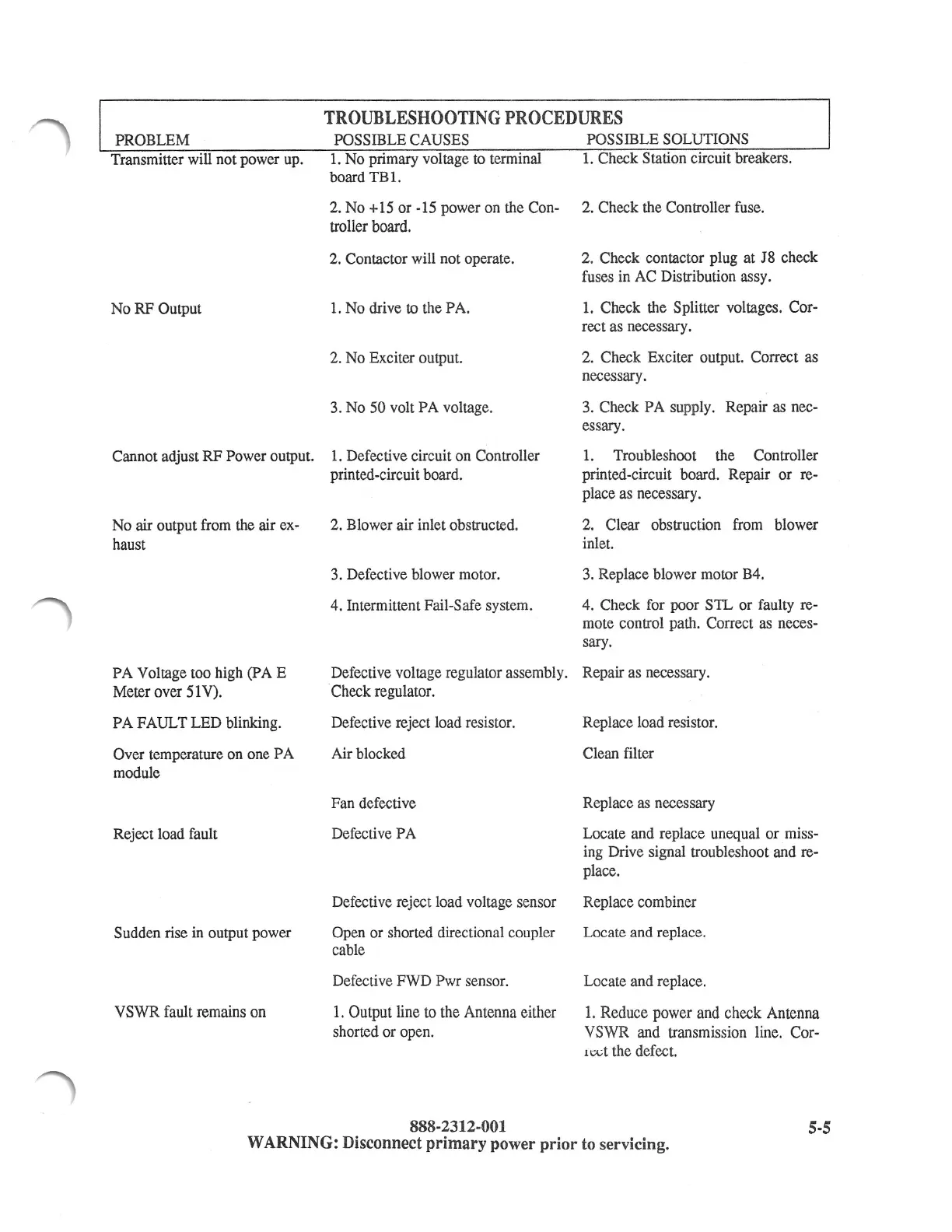
TROUBLESHOOTING
PROCEDURES
PROBLEM POSSIBLE CAUSES POSSIBLE SOLUTIONS
Transmitter will not power up.
1.
No primary voltage to terminal
board
TBl.
1.
Check Station circuit breakers.
No RF Output
2. No +15 or -15 power on the Con- 2. Check the Controller fuse.
troller board.
2. Contactor will not operate. 2. Check contactor plug at J8 check
fuses in AC Distribution assy.
1.
No drive to the PA.
2. No Exciter output.
3. No 50 volt
PA
voltage.
1.
Check the Splitter voltages. Cor-
rect as necessary.
2. Check Exciter output. Correct as
necessary.
3. Check PA supply. Repair as nec-
essary.
Cannot adjust
RF
Power output.
1.
Defective circuit on Controller
printed-circuit board.
1.
Troubleshoot the Controller
printed-circuit board. Repair
or
re-
place as necessary.
No air output from the air ex- 2. Blower air inlet obstructed.
2. Clear obstruction from blower
inlet. haust
PA
Voltage too high
(PAE
Meter over 51V).
PA
FAULT LED blinking.
Over temperature on one
PA
module
Reject load fault
Sudden rise
in
output power
VSWR fault remains on
3. Defective blower motor.
4. Intermittent Fail-Safe system.
3.
Replace blower motor B4.
4. Check for poor
S1L
or faulty re-
mote control path. Correct as neces-
sary.
Defective voltage regulator assembly. Repair as necessary.
Check regulator.
Defective reject load resistor.
Air blocked
Fan defective
Defective PA
Replace load resistor.
Clean filter
Replace as necessary
Locate and replace unequal or miss-
ing Drive signal troubleshoot and re-
place.
Defective reject load voltage sensor Replace combiner
Open or shorted directional coupler
cable
Defective FWD Pwr sensor.
1.
Output line to the Antenna either
shorted or open.
888-2312-001
Locate and replace.
Locate and replace.
1.
Reduce power and check Antenna
VSWR and transmission line. Cor-
11Xt
the defect.
5-5
WARNING: Disconnect
primary
power
prior
to servicing.