www.SteamPoweredRadio.Com
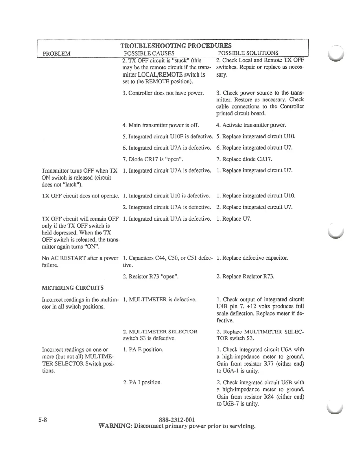
TROUBLESHOOTING
PROCEDURES
PROBLEM
POSSIBLE CAUSES
2. TX OFF circuit
is
"stuck" (this
may be the remote circuit
if the trans-
mitter
LOCAL/REMOTE
switch
is
set
to
the REMOTE position).
3. Controller does not have power.
4. Main transmitter power is off.
POSSIBLE SOLUTIONS
2. Check Local and Remote TX OFF
switches. Repair or replace
as
neces-
sary.
3. Check power source to the trans-
mitter. Restore
as
necessary. Check
cable connections to the Controller
printed circuit board.
4. Activate transmitter power.
5. Integrated circuit
Ul0F
is defective. 5. Replace integrated circuit UlO.
6. Integrated circuit U7 A is defective. 6. Replace integrated circuit U7.
7.
Diode CR17 is "open". 7. Replace diode CR
17.
Transmitter turns OFF when TX
1.
Integrated circuit U7 A
is
defective.
1.
Replace integrated circuit U7.
ON switch is released (circuit
does not "latch").
TX OFF circuit does not operate.
1.
Integrated circuit UlO is defective.
1.
Replace integrated circuit UlO.
2. Integrated circuit U7 A is defective.
2.
Replace integrated circuit U7.
TX OFF circuit will remain OFF
1.
Integrated circuit U7 A is defective.
1.
Replace U7.
only if the TX OFF switch is
held depressed. When the TX
OFF switch is released, the trans-
mitter again turns "ON".
No
AC
RESTART after a power
1.
Capacitors C44, C50, or C51 defec-
1.
Replace defective capacitor.
failure. tive.
2. Resistor R73 "open".
METERING
CIRCUITS
Incorrect readings in the multim-
1.
MULTIMETER
is
defective.
eter in all switch positions.
2.
MUL
TIMEIBR
SELECTOR
switch
S3
is defective.
Incorrect readings on one or
1.
PAE
position.
more (but not all) MUL TIME-
TER SELECTOR Switch posi-
tions.
2. PA I position.
5-8
888-2312-001
2.
Replace Resistor R73.
1.
Check output
of
integrated circuit
U4B pin
7.
+12 volts produces full
scale deflection. Replace meter
if
de-
fective.
2. Replace
MULTIMETER
SELEC-
TOR switch S3.
1.
Check integrated circuit U6A with
a high-impedance meter to ground.
Gain from resistor R77 (either end)
to
U6A-1 is unity.
2.
Check integrated circuit U6B with
a high-impedance meter to ground.
Gain from resistor R84 (either end)
to
U6B-7
is
unity.
WARNING: Disconnect primary power prior to servicing.