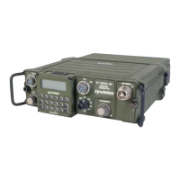
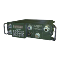
RF-5800H 125-WATT COMMUNICATION SYSTEM
GENERAL INFORMATION
1-2
1.3.2 Level II
The maintenance technician repairs the radio system by utilizing a System (Level II) manual to fault isolate to the
faulty unit (for example, receiver-transmitter, power amplifier, antenna coupler, etc.). The faulty LRU is replaced
with a spare and sent to Maintenance Level III.
1.3.3 Level III
The faulty unit is serviced at a facility that has support equipment available, typically a hot test bed radio system.
The suspected faulty unit is inserted into the hot test bed radio system to isolate the faulty assembly using a
Maintenance (Level III) manual. The faulty SRU or module is replaced with a spare and passed to Maintenance
Level IV.
1.3.4 Level IV
The faulty SRU or module is returned to Harris/RF Communications for repair. If Level IV maintenance
capabilities are available on-site, the maintenance technician can identify the faulty component on the SRU using
a Depot Maintenance (Level IV) manual that outlines the electronic maintenance techniques and test fixtures
necessary to repair the SRU.
 Loading...