Do you have a question about the Harris RF-5800H and is the answer not in the manual?
Specifies the manual's purpose: guiding installation and maintenance.
Cross-references safety precautions and recommends thorough review before procedures.
Explains the four maintenance levels and how they relate to support documentation.
Details maintenance tasks for Level II, focusing on fault isolation and unit replacement.
Describes Level III maintenance, involving hot test beds and shop replaceable units.
Covers Level IV maintenance for component repair on shop replaceable units.
Guarantees equipment repair/replacement due to defects and warrants repair service.
Identifies system configurations and refers to descriptions of vehicular, base station, and transit case systems.
Describes the vehicular system, its components, and related figures/family trees.
Details the base station system, its components, and associated figures/family trees.
Explains the transit case system, its components, and related figures/family trees.
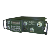
Describes the individual units that comprise the RF-5800H system configurations.
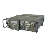
Describes the RF-5833H-PA power amplifier, its features, and operation.
Details the RF-382A automatic antenna coupler, its capabilities, and tuning times.
Provides general guidelines for setting up the system, considering factors like power, noise, and ventilation.
Presents grounding guidelines for vehicular and base station installations, with warnings and cautions.
Details grounding procedures for base station and transit case systems, including pipe/rod grounding.
Introduces sections on power requirements, ancillary kits, cabling, and installation procedures.
Details power requirements for base station, transit case, and vehicular systems.
Refers to figures for unit installation diagrams for vehicular, transit case, and base station configurations.
Outlines the process for verifying correct system installation before powering up.
Details pre-power up checks for connectors, grounding, hardware, cooling, power source, and antenna.
Describes the procedure for powering up the system and executing the Built-In Test (BIT).
States that there are no special operating procedures at Level II maintenance.
Describes the signal flow within the system, including RF/Audio, Control, and Power Distribution.
Details the RF/Audio signal path, from handset to antenna or coupler.
Describes the power distribution for vehicular and base station systems.
Outlines systematic daily and weekly checks to prevent equipment failure and reduce downtime.
Details troubleshooting procedures, including maintenance turn-on, BIT, and non-BIT methods.
Provides procedures for troubleshooting non-Built-In Test faults based on symptoms and recommended actions.
Explains how to execute BIT from the KDU and interpret fault codes for LRU identification.
Provides support data including protective device index and troubleshooting index.
References functional areas, figures, and descriptions for isolating problems to LRUs.
Presents parts lists for Line Replaceable Units (LRUs) across various system configurations.
Provides detailed technical specifications for the RF-5833H-PA 150-Watt Power Amplifier.
Definition of Built-In Test.
Definition of Lowpass Filter.
Definition of Line Replaceable Unit (Units in this manual).
Definition of Power Amplifier.
Definition of Radio Frequency.
Definition of Radio Frequency Interference.
Definition of Receiver-Transmitter.
Definition of Troubleshooting Analysis Procedure.
Definition of Very High Frequency.
| Brand | Harris |
|---|---|
| Model | RF-5800H |
| Category | Conference System |
| Language | English |