2-23
RF-5800H 150-WATT COMMUNICATION SYSTEM
INSTALLATION
2.6 INSTALLATION CHECKOUT
Installation checkout has three phases. Paragraph 2.6.1 is a pre-power up check to make sure the system is installed
correctly, and that all support items are available. Paragraph 2.6.2 covers the RF-5800H 150-Watt Communication
System power up.
2.6.1 Inspection Before Power Up
When the RF-5800H 150-Watt Communication System is installed and all connector cables are attached, verify that
the following items are completed:
• All connectors are attached and associated hardware is secure.
• System units are connected to ground, preferably at a single point.
• Ground straps are connected between the radio system units and a known good ground.
• Ensure all hardware is tightened.
• Area cooling is adequate for removing heat that may develop during equipment operation.
• Power source is of adequate capability and adequately protected for the radio system's load, and that
installation of the power cable is correct.
• Antenna is in place, correctly connected, and protected against accidental contact.
• Companion equipment, such as the RF-5051PS, or remote control, are in operational readiness condition.
2.6.2 Initial Settings and Power Up
Perform the following procedure to power up the RF-5800H-MP and RF-5833H-PA and execute Built-In Test (BIT):
a. If the system is vehicular, skip this step and proceed directly to Step b On the RF-5051PS, set the power
switch to the ON position.
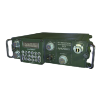
b. ?On the RF-5833H-PA, set switch CB1 to the ON (up) position.
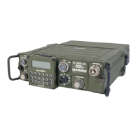
c. On the RF-5800H-MP, set the function switch to the PT position.
d. On the RF-5800H-MP, press the OPT pushbutton.
e. If necessary, press the left/right arrow pushbuttons to select the TEST field.
NOTE
While in TEST mode, the RF-5800H-MP cannot receive or
transmit.
f. Press the ENT pushbutton.
g. If necessary, press the left/right arrow pushbuttons to select the ALL field.
h. Press the ENT pushbutton.
i. If the unit passes BIT, place in service. If a BIT code is displayed, refer to the following paragraphs.
If the RF-5800H-MP displays a fault code on the Liquid Crystal Display (LCD) after completing the
BIT test, record the fault code and proceed to Paragraph 6.2.4, BIT Troubleshooting.
 Loading...