M
Morgan KramerAug 15, 2025
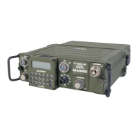
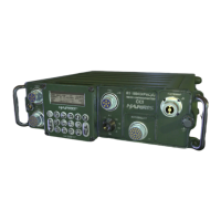
What to do if Harris Conference System displays PA OVERTEMP or THERMAL WARNING?
- AAmy BakerAug 15, 2025
If your Harris Conference System displays PA OVERTEMP or THERMAL WARNING, unkey the RF-5800H-MP and allow the RF-5832H-PA to cool. Ensure the RF-5832H-PA is well-ventilated and not in direct sunlight. If the problem continues, replace the RF-5832H-PA.