7-4
RF-5800H 150-WATT COMMUNICATION SYSTEM
PARTS LIST
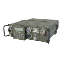
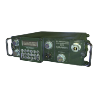
7.3 LRU DIAGRAMS
Figure 7-1 through Figure 7-11 show the LRUs within each system configuration identified in Table 7-1 through
Table 7-9. Optional cables for the system are listed in Table 7-10 and shown in Figure 7-12 through Figure 7-20.
Cable Assembly, Y, ASCII Remote PA
Control
10535-0730 - - Figure 7-16
Cable Assembly, KG-84C Black Data 10535-0750 - - Figure 7-17
Cable Assembly, ASCII remote control Rear
D-Connector
10535-0760 - - Figure 7-18
Cable Assembly, Sync/Async RS-232 DTE
Data
10535-0770 - - Figure 7-19
Cable Assembly, Synchronous RS-232 DTE
Data (DB-25)
10535-0780 - - Figure 7-20
Table 7-10. Available Option Cables (Purchased Separately) (Continued)
Item Name Part
Number
Quantity Figure
Number
 Loading...