25 – English
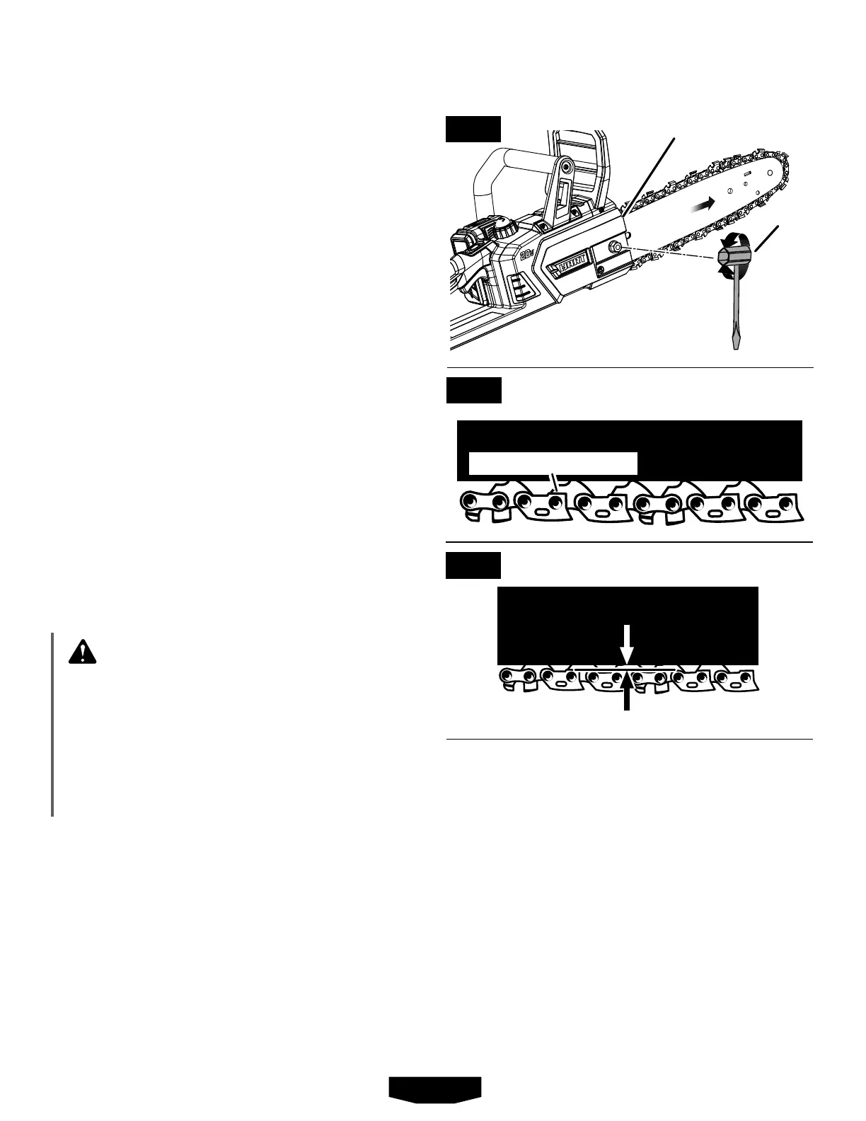
FLATS ON TIE STRAPS
Removealltheslackfromthechainbyturning
thechaintensioningscrewclockwiseuntilthe
chainseatssnuglyagainstthebarwiththedrive
linksinthebargroove.
Liftthe tip of the guidebarup to check for
sag.Releasethetipoftheguidebarandturn
thechaintensioningscrew1/2turnclockwise.
Repeatthisprocessuntilsagdoesnotexist.
Holdthetipoftheguidebarupandtightenthe
bar mounting screw securely.
Chainiscorrectlytensionedwhenthereisno
sagontheundersideoftheguidebar,thechain
issnug,butitcanbeturnedbyhandwithout
binding.
NOTE:Ifchainistootight,itwillnotrotate.
Loosenthechaincoverscrewslightlyandturn
tensionadjuster1/4turncounterclockwise.Lift
thetipoftheguidebarupandretightenchain
coverscrewsecurely.Assurethatthechainwill
rotatewithoutbinding.
Placethehexkeybackintothestoragearea.
ADJUSTING CHAIN TENSION
See Figures 29 - 30.
WARNING:
Shutoffthemotor,waitforallmovingpartsto
stop,andremovethebatterypack.Nevertouch
oradjustthechainwhiletheengineisrunning.
Thesawchainisverysharp.Alwayswear pro-
tectivegloveswhen performingmaintenance
on thechain. Failuretofollowtheseinstructions
canresultinseriouspersonalinjury.
Properchaintensioniscriticaltotheperformance
ofyour chain saw. Always check chain tension
beforeusingthe saw and periodically until the
workiscomplete.
Acoldchainiscorrectlytensionedwhenthereis
noslackontheundersideoftheguidebar.The
chainshouldbesnug,butstillabletobeturned
byhandwithoutbinding.
MAINTENANCE
SCRENCH
APPROX. .050 in.
Awarmchainiscorrectlytensionedwhentheflats
onthetiestrapshangapproximately.050inches
outofthebargroove.
If adjustment is needed:
Loosenthechaincoverscrewtofingertight.
Raisethetipoftheguidebarandcontinueto
holdupuntiltheendofthisprocedure.
Turnthechaintensioningscrewclockwiseuntil
theflatsonthetiestrapsofthechaincontact
thebar,makingsurethedrivelinksareseated
insidethebargroove.
CHAIN COVER
SCREW
FIG. 28
FIG. 29
FIG. 30

 Loading...