EN DE
13
NOTE! Due to thermal embrittlement, the use
of PVC-insulated wire as the connecting cable
of the heater is forbidden.
• If the connecting and installation cables are
higherthan1000mmfromtheoorinthesauna
or inside the sauna room walls, they must be able
to endure a minimum temperature of 170 °C
when loaded (for example, SSJ). Electrical
equipment installed higher than 1 000 mm from
thesaunaoormustbeapprovedforuseina
temperature of 125 °C (marking T125).
• In addition to supply connectors, the PC/-
H/-F heaters are equipped with a connector
(P), which makes the control of the electric
heatingpossible(gure7).Voltagecontrolis
transmitted from the heater when it is switched
on. The control cable for electrical heating is
brought directly into the junction box of the
heater, and from there to the terminal block of
the heater along a rubber cable with the same
cross-section area as that of the connecting
cable.
3.3.1. Electric Heater Insulation Resistance
Whenperformingthenalinspectionoftheelectrical
installations, a “leakage” may be detected when
measuring the heater’s insulation resistance. The
reason for this is that the insulating material of the
heating elements has absorbed moisture from the
air (storage, transport). After operating the heater
for a few times, the moisture will be removed from
the heating elements.
Do not connect the power feed for the heater
through the RCD (residual current device)!
3.3.2. Installation of the Control Unit and Sensor
(PC-E/HE)
• The control unit includes detailed instructions
for fastening the unit on the wall.
• Installthesensor(WX248)asshownin
chendes Kabel verwendet. ACHTUNG! PVC-
isolierte Kabel dürfen wegen ihrer schlechten
Hitzebeständigkeit nicht als Anschlusskabel des
Saunaofens verwendet werden.
• Falls der Anschluss oder die Montagekabel
höher als in 1 000 mm Höhe über dem Boden
in die Sauna oder die Saunawände münden,
müssen sie belastet mindestens eine Tempera-
tur von 170 °C aushalten (z.B. SSJ). Elektroge-
räte, die höher als 1 000 mm vom Saunaboden
angebracht werden, müssen für den Gebrauch
bei 125 °C Umgebungstemperatur zugelassen
sein (Vermerk T125).
• Die PC/-H/-F-Saunaöfen sind zusätzlich zum
Netzanschluss mit einer Klemme (P) ausge-
stattet, welche die Möglichkeit zur Steuerung
der Elektroheizung bietet (Abb. 7). Der Ofen
übernimmt mit dem Einschalten die Span-
nungsregelung.Das Steuerungskabel für die
Elektroheizung wird direkt zur Klemmdose des
Saunaofens gelegt und von dort aus durch ein
Gummikabel der gleichen Stärke weiter zur Rei-
henklemme des Saunaofens geleitet.
3.3.1. Isolationswiderstand des Elektrosaunaofens
Bei der Endkontrolle der Elektroinstallationen kann
bei der Messung des Isolationswiderstandes ein
“Leck” auftreten, was darauf zurückzuführen ist,
dass Luftfeuchtigkeit in das Isolationsmaterial der
Heizwiderstände eingetreten ist (bei Lagerung und
Transport). Die Feuchtigkeit entweicht aus den Wi-
derständen nach zwei Erwärmungen.
Schalten Sie den Netzstrom des Elektrosau-
naofens nicht über den Fehlerstromschutz-
schalter ein!
3.3.2. Anschluß des Steuergerätes und der Fühler
(PC-E/HE)
• In Verbindung mit dem Steuergerät werden
genauere Anweisungen zu dessen Befestigung
an der Wand gegeben.
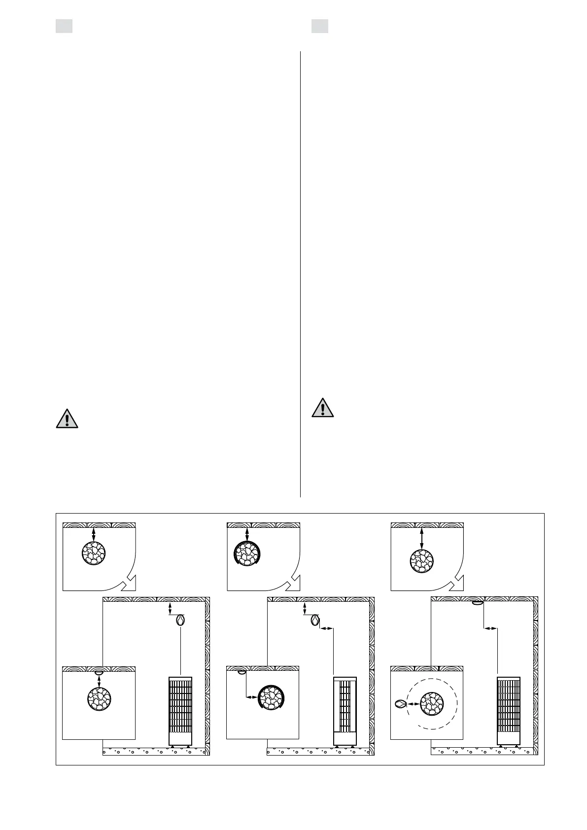
Figure 8. Installing the sensor (all dimensions in millimeters)
Abbildung 8. Installation der Fühler (alle Abmessungen in Millimetern)
100
100
100
100
100
100
PC/-E
PC-H/-HE/-F
PC-H/-HE/-FPC/-E
>
100
100
30-100
100