EN DE
22
3. INSTRUCTIONS FOR INSTALLATION
3. MONTAGEANLEITUNG
3.1. Before Installation
Before installing the heater, study the instructions
for installation. Check the following points:
• Is the output and type of the heater suitable for
the sauna room? The cubic volumes given in
table 2 should be followed.
• Is the supply voltage suitable for the heater?
• The location of the heater fulfils the minimum
requirements concerning safety distances given
in fig. 4 and table 2.
Note! Only one electrical heater may be installed in
the sauna room. The heater should be installed so
that the warning texts can also be read without dif-
ficulty after the installation.
3.1. Vor der Montage
Lesen Sie die Montageanleitung, bevor Sie den Sau-
naofen installieren. Überprüfen Sie die folgenden
Punkte:
• Ist der zu montierende Saunaofen in Leistung
und Typ passend für die Saunakabine? Die
Rauminhaltswerte in Tabelle 2 dürfen weder
übernoch unterschritten werden.
• Ist die Netzspannung für den Saunaofen geeignet?
• Der Montageort des Ofens er füllt die in Abb. 4
und Tabelle 2 angegebenen Sicherheitsmindest-
abstän de.
ACHTUNG! In einer Sauna darf nur ein Saunaofen
installiert werden. Der Saunaofen muß so installiert
werden, daß die Warnanweisungen nach der Mon-
tage leicht lesbar sind.
Heater
Ofen
Output
Leistung
Mitat
Mått
Stones
Steine
Sauna room
Saunakabine
Width/Depth/Height
Breite/Tiefe/Höhe
Weight/
Gewicht
Cubic vol.
Rauminhalt
Height
Höhe
kW mm kg max. kg
2.3.!
min. m³ max. m³ min. mm
HL70 6,8 415/340/810 21 50 5 10 1900
HL90 9,0 415/340/810 21 50 8 14 1900
HL110 10,8 415/410/810 24 70 9 18 1900
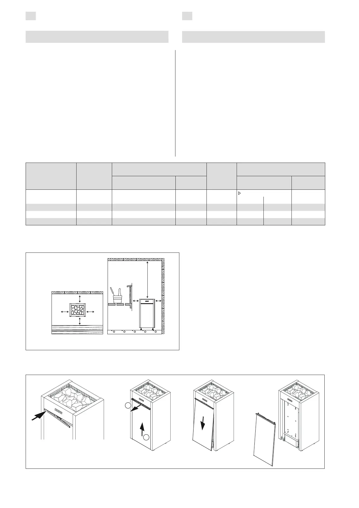
Table 2. Installation details of the heater
Tabelle 2. Montageinformationen zum Saunaofen
Figure 5. Opening the cover of the service hatch
Abbildung 5. Öffnen der Serviceabdeckung
30
30 30
30 30
1100
30
Figure 4. Safety distances (all dimensions in millimeters)
Abbildung 4. Sicherheitsmindestabstände (alle Abmessungen in Millimetern)
2
1