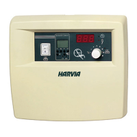
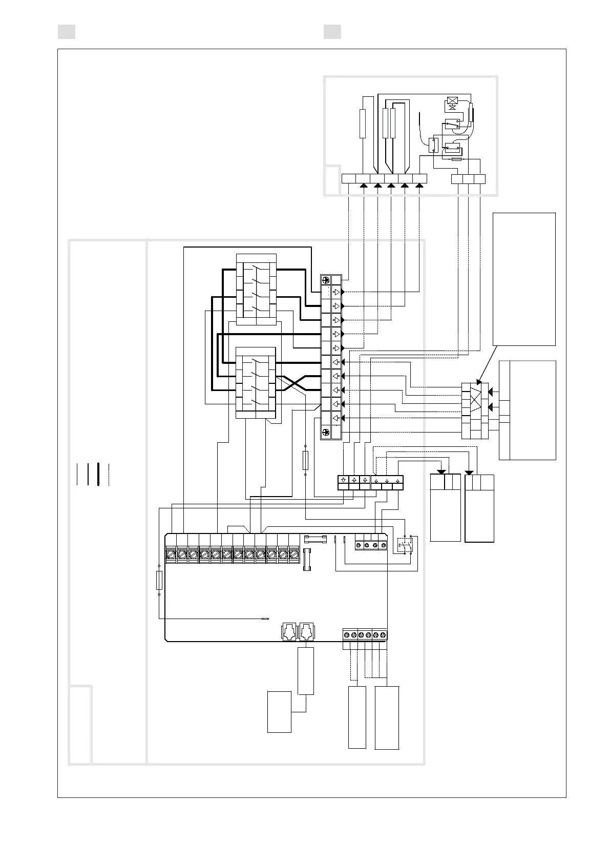
Figure 6a. Electrical connections 240 V, 1Ph (CX30C-U1)
Figure 6a. Connexions électriques 240 V, 1Ph (CX30C-U1)
1 2 3 4
1 2 3 4
A2
A1
K1
S
L
N
GND
Fan/Ventilateur
120 V 1Ph
Max 100 W
L
N
GND
Lighting/Éclairage
120 V 1Ph
Max 100 W
X7
X5
X3
6
5
4
3
2
1
F2
F1
CX30C-U1
1 2 3 4
1 2 3 4
A2
A1
K2
PK A1L2L2 L1L1
GND
W1
N
N
N
N L1
L2
L3
U
W1
P
W
V
NN
N
N
K
U2U1
U2
U1
A1 P
L1
L1 L2 L2
W1
L2L1
L2
L1
F3
F3
F3
H2 = Combi heater / Poêle combi
H2
Main electrical panel/
Panneau électrique principal
240 V 1Ph
Max 30 A per cable /
par câble
GND N L1 L2
GND N L1 L2 L1 L2
GND N L1 L2
White/Blanc
Red/Rounge
Blue/Bleu
Yellow/Jaune
Blue/Bleu
Brown/Brun
K1 = K2 = Contactors/Contacteurs (30A)
S = Main switch/Commutateur principal
F1 = Breaker/Fusible T2.5AH
F2 = Breaker/Fusible T40mA
F3 = Breaker/Fusible 10A
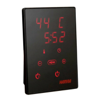
Data cable/
Câble de données
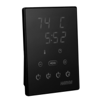
Control panel/
Tableau de
commande
Temperature sensor/
Capteur de
température
Humidity sensor/
Capteur d'humidité
Factory wiring/Câblage eectué en usine (AWG 18)
Factory wiring/Câblage eectué en usine (AWG 12)
Factory wiring/Câblage eectué en usine 2 x (AWG 12)
Installation wiring/Câblage eectué à l’installation
240V
1Ph
120V 1Ph
2 pole 2 breaker subpanel load center
shall be supplied by electrical contractor./
Un panneau de distribution de sous tableau à 2 pôles et
2 disjoncteurs doit être fourni par l’électricien.
2 grouped heaters/2 poêles groupés
 Loading...