10
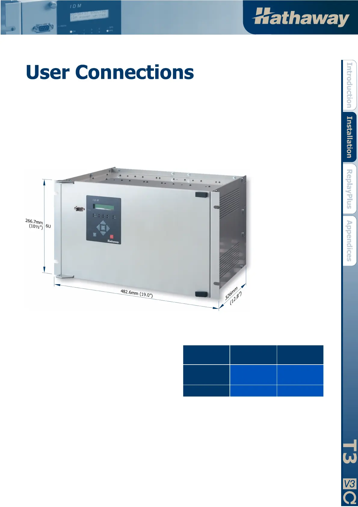
IDM T3 DAU Dimensions
System Layout
A dimensioned picture of the 6U rack mounting IDM T3 DAU
is shown below. It is an easy device to mount. All analog, event
and alarm signal conditioning is internal to the chassis. All input
signal connections to the device are via screw terminal blocks
on the rear panel. The IDM is small enough to mount directly
into the protection panel of the equipment being monitored.
Input / Output Connections
See IDM T3 DAU Rear picture, next page.
Power Supply and Earthing
The standard DAU power supply is a universal input with the
following ranges:
# 80V to 300Vdc
# 110V to 220Vac, 50/60Hz
The burden of each DAU is 40VA.
The power is connected to terminals 1 and 2 on TB8. The labels
L and N are for live and neutral of an AC supply. The labels +
and – show the polarity of the DC supply.
It is very important to connect an earth to the main earth stud.
This earth stud should be connected to the system substation
earth.
An on / off toggle switch is provided on the rear panel to switch
the power to the DAU.
Analog Inputs
Each DAU has 16 analog
inputs connected to
#1TB1,
#1TB2, #1TB3 and #1TB4.
Channels 1 to 16 are AC
coupled via interposing
transformers mounted inside
the 6U chassis.
The AC coupled inputs can
be configured at the factory
for voltage or current. The
DAU configuration sheet
provided at the back of this
manual will confirm the
channel allocation.
The sensitivity of the analog
channels is given in the
following table:
CHANNEL
TYPE
NOMINAL
VALUES
FULL SCALE
DEFLECTION
AC Voltage 63.5V or 110V
80V, 130V or
260V
AC Current 1A or 5A 20 x nominal
Selection of the nominal value is via a link on the internal signal
conditioning board in each DAU. These links are set in the
factory to customer requirements and full details are included on
the DAU configuration sheet provided at the back of this
manual.
 Loading...