Do you have a question about the Hatz Diesel 4 H50 TIC and is the answer not in the manual?
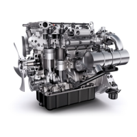
Illustrates components on the intake side of the engine, including air intake, filters, and lifting eyes.
Details components on the exhaust side of the engine, featuring turbocharger, catalytic converter, and radiator.
Provides key specifications for the engine, including dimensions, capacities, and operating parameters.
Explains the data found on the engine's identification plate, including model, serial number, and output.
Diagram and component identification for the engine's oil lubrication system.
Schematic representation of the engine's cooling system flow.
Visualizes the cooling system's internal pathways and component connections within the engine block.
Illustrates the cooling circuit's interaction with the radiator and cabin heating system.
Depicts the cooling system integration with exhaust gas recirculation and oil cooling.
Lists recommended sealants and adhesives with their part numbers and application details.
Identifies specialized tools required for cylinder head assembly/disassembly and exterior engine work.
Lists special tools needed for general engine assembly and disassembly procedures.
Details specialized tools for servicing individual engine components.
Describes equipment used for setting up test benches for engine diagnostics and evaluation.
Lists additional components and fixtures for configuring engine test bench setups.
Identifies tools for adjusting engine parameters and performing diagnostic measurements.
Lists further specialized equipment for engine adjustment and diagnostic tasks.
Details specialized tools for the engine's cooling system, such as filling devices.
Lists specialized tools for working with the engine's electrical components and connections.
Details the installation and specifications of the main fuel filter.
Illustrates the suction hose and its connection points on the engine.
Provides installation details for the oxidation catalytic converter and its fastening.
Details the installation and tensioning of the alternator and poly V-belt.
Shows the mounting procedure and specifications for the starter motor.
Illustrates the installation of the engine base, including sealant and screw specifications.
Details the installation of the oil cooler and its associated components.
Shows the routing and fastening of hoses for the oil cooler system.
Illustrates the mounting of the fan and its securing hardware.
Shows the cylinder crankcase with dipstick, oil pressure sensor, and check valve.
Details the installation of pins, valves, and connectors on the cylinder crankcase.
Illustrates the piston cooling system components and valve screw installation.
Details the installation of main bearing halves and thrust washers for the crankshaft.
Explains the process of threading the crankshaft into the cylinder block and ensuring axial play.
Specifies the sequence and torque for tightening crankshaft main bearing brackets.
Details the lubrication and insertion of the camshaft into the cylinder block.
Shows the placement and spring pin insertion for the crankshaft gear wheel.
Illustrates applying sealant and installing a radial shaft seal on the connector housing.
Details the procedure for mounting the connector housing using special tools and specified torque.
Provides instructions for mounting the flywheel, including sprocket placement and sensor precautions.
Details the assembly of the oil pump, including seal lubrication and screw tightening.
Shows the mounting of the pulley, including tension washer and cylinder screw specifications.
Details the connection of piston to conrod, bearing installation, and conrod screw tightening.
Illustrates the installation of the intake manifold, including sealant and screw specifications.
Details the application of sealant and installation of the oil sump with screw connections.
Shows the mounting of the water pump with spring pins and cylinder screws.
Details the use of special tools for installing roller tappets and guide pins.
Illustrates valve components and the use of a special tool for inserting/removing valves.
Guide for selecting the correct cylinder head seal based on piston protrusion measurements.
Specifies the multi-stage tightening process and torque for cylinder head screws.
Details the assembly of rocker arm bearing blocks, adjusting rings, and play measurement.
Explains the procedure for setting the basic tappet clearance using adjusting screws.
Details the installation of the cylinder head cover, including gasket and screw plug.
Shows the installation of glow plugs, including torque and high-temperature paste application.
Details the mounting of the thermostat housing, temperature sensor, and O-ring.
Illustrates the installation of the exhaust manifold with gaskets, nuts, and sealing rings.
Details the mounting of the turbocharger, including oil lines and gaskets.
Shows the installation of the lifting eye with cylinder screws.
Details the pre-mounting and tightening sequence for the exhaust gas return components.
Illustrates the placement of AGR cooler, housing, and bracket for exhaust gas return.
Specifies the tightening sequence and torque for exhaust gas return system fasteners.
Shows the routing and clamping of hoses for the exhaust gas return system.
Details the installation of the pressure-temperature sensor for the exhaust gas return.
Provides general guidelines for working on the injection system, emphasizing cleanliness and safety.
Describes the procedure for mounting and dismounting injectors and fuel return lines.
Explains the correct positioning of the high-pressure pump using crankshaft markings.
Details the mounting of the high-pressure pump using flange bolts.
Illustrates the installation of fuel lines and the high-pressure rail with specified torques.
Shows the fuel pressure tube connections to the CR injectors and their tightening.
Details the installation of the crankcase ventilation system, including the Provent and hose connections.
Provides a table of standard screw tightening torques based on thread size and screw quality.
Illustrates specific screw tightening torques applied to engine components.
Shows torque values for various fasteners during engine assembly.
Lists electrical components and their identifiers used in wiring diagrams.
Continues the list of electrical components and their designations for wiring diagrams.
Details the terminal designations and their corresponding functions for HATZ cable marking.
Cross-references Bosch designations with HATZ and English designations for cable marking.
Illustrates the maximum configuration of the cable harness with component connections.
Illustrates the minimum configuration of the cable harness with component connections.
Schematic diagram of the electrical system for the standard 12V configuration.
Details the CAN speed adjustment system, including hand lever, gas pedal, and rotary knob.
Explains the analog speed adjustment system with pin assignments for harness connectors.
Illustrates the correct cable routing for the Diesel Particulate Filter (DPF) system.
General guidance on routing electrical cables within the engine compartment.
Provides a table of blink codes, their error sources, and recommended remedies for diagnostics.
Graph showing charge current versus engine speed at different ambient temperatures for a 12V system.
Graph showing charge current versus engine speed at different ambient temperatures for a 24V system.
| Brand | Hatz Diesel |
|---|---|
| Model | 4 H50 TIC |
| Category | Engine |
| Language | English |