Page 4 For technical questions, please call 1-888-866-5797. Item 57720
SAFETY OPERATION MAINTENANCEASSEMBLY
Assembly Instructions
Read the ENTIRE IMPORTANT SAFETY INFORMATION section at the beginning of this
manual including all text under subheadings therein before set up or use of this product.
Note: For additional information regarding the parts listed in the
following pages, refer to Parts List and Diagram on page 10.
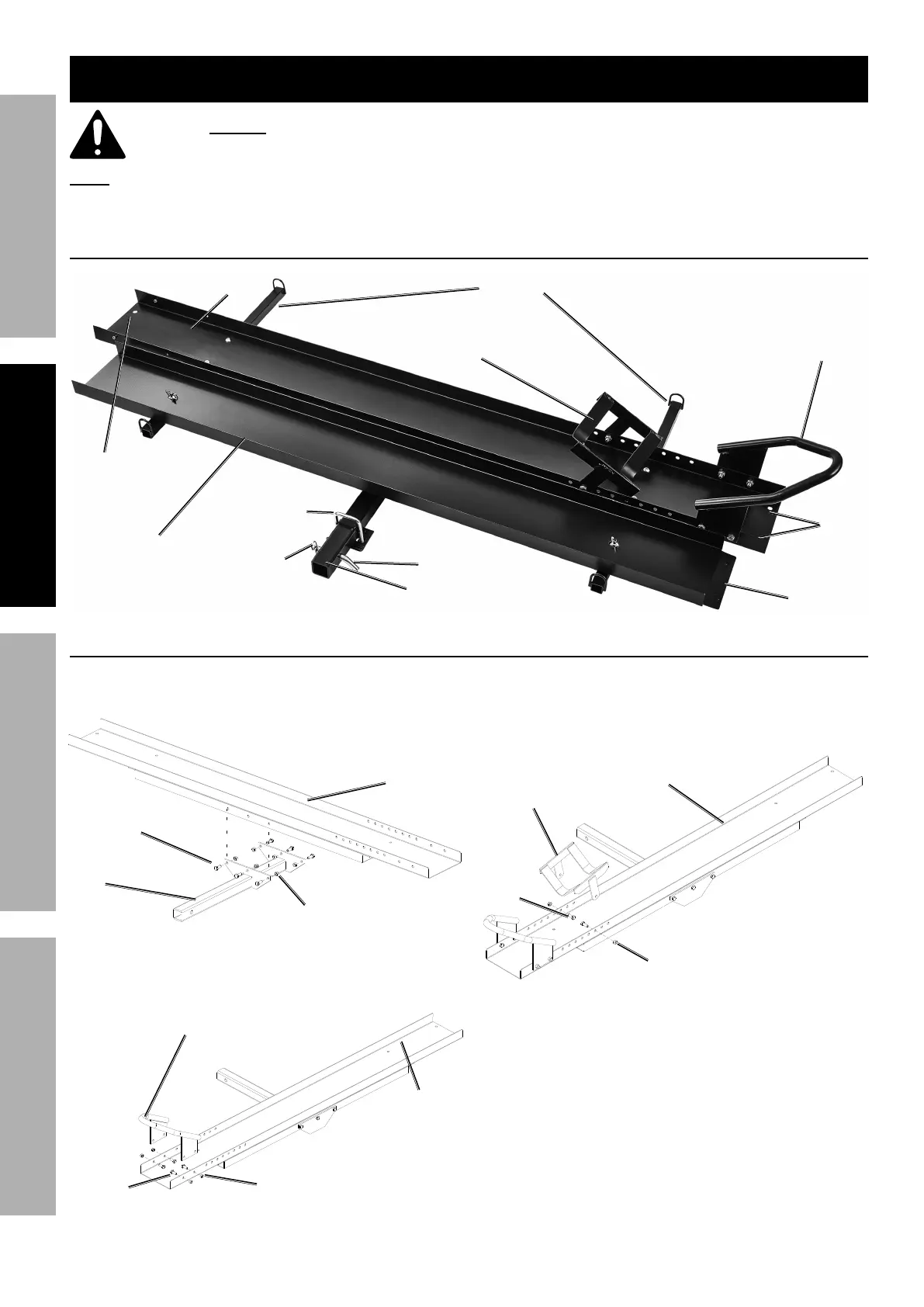
Components
Hitch Tube
Hook Tube
Carrier Support
(not shown)
Wheel Chock
Front Fame
Carrier Frame
Wheel Chock Dropleaf
Ramp
Ramp
Hooks
Ramp
Hook
Holes
Hitch Pin
Hitch R-Clip
U-Bolt and
Stabilizer Plate
Carrier Assembly
1. Secure the Hitch Tube (12) to Carrier Frame (6) with
six Hex Bolts (5) and six Nuts (4). See Figure A.
Carrier
Frame (6)
Nut (4)
Hitch Tube (12)
Hex Bolt (5)
Figure A: Hitch Tube Installation
2. Attach Wheel Chock Front Frame (1) to
Carrier Frame (6) with four Hex Bolts (5)
and four Nuts (4). See Figure B.
Carrier
Frame (6)
Wheel Chock Front Frame (1)
Hex
Bolt (5)
Nut (4)
Figure B: Wheel Chock Front Frame Attachment
3. Attach Wheel Chock Dropleaf (2) to
Carrier Frame (6) with two Hex Bolts
(5) and two Nut (4). Install Dropleaf
according to tire size. See Figure C.
Carrier Frame (6)
Wheel Chock
Dropleaf (2)
Hex
Bolt (5)
Nut (4)
Figure C: Wheel Chock Dropleaf Attachment