USE ONLY HAYWARD GENUINE REPLACEMENT PARTS
3
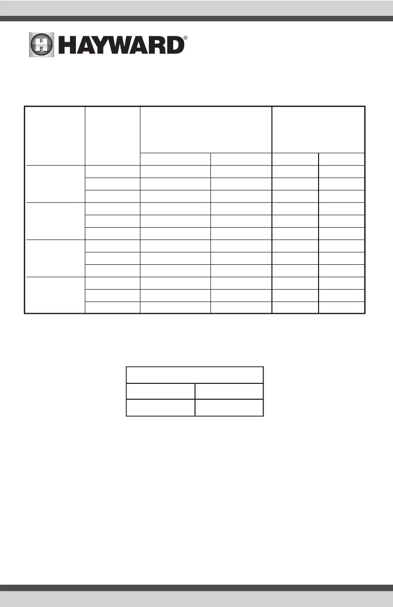
Using the chart below to determine correct cam setting using standard clock positions. Refer to
the “Cam Adjustment” section in this manual to change upper and lower cam positions if neces-
sary.
Two Port Valve
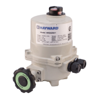
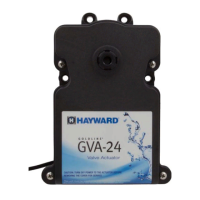
The Model GVA-24 Actuator may be mounted to the valve in four different positions. In all cases,
the cam settings are the same. Refer to the chart below for cam settings for 2 way valves.
Mounting Instructions
If the valve is plumbed with Port 2 as the common port and the main body of the actuator is
mounted over Port 2 (standard mounting), there is no need to adjust the actuator cams.
1. Remove Locking Knob and handle. Set aside for reinstallation later.
2. Remove four (4) screws from the valve. Refer to the image on page 2 (mounting positions) to
determine which screws to remove.
3. On the back side of the actuator, align the smallest slot on the actuator shaft with the smallest
slot on the valve diverter.
4. With the two shafts engaged rotate the actuator until holes on the actuator align with the
screw holes on the cover.
GVA
MOUNTING
OPTION
PORT
WHERE
WATER
ENTERS
CAM SETTING
PORT WHERE
WATER EXITS
LOWER CAM UPPER CAM PORT PORT
1 6 o'clock 9 o'clock 2 3
A
2 (std) 12 o'clock 12 o'clock 1 3
(Standard)
3 3 o'clock 6 o'clock 1 2
1 9 o'clock 12 o'clock 2 3
B
2 3 o'clock 3 o'clock 1 3
3 6 o'clock 9 o'clock 1 2
1 3 o'clock 6 o'clock 2 3
C
2 9 o'clock 9 o'clock 1 3
3 12 o'clock 3 o'clock 1 2
1 12 o'clock 3 o'clock 2 3
D
2 6 o'clock 6 o'clock 1 3
3 9 o'clock 12 o'clock 1 2
CAM SETTIN G
LOWER CAM UPPER CAM
3 o'clock 6 o'clock
 Loading...