Mounting the Equipment
VS Omni Hub
The Hub is contained in a raintight enclosure
that is suitable for outdoor mounting. It must
be mounted a minimum of 6 ft (2 meters) hori-
zontal distance from the pool/spa (or more, if
local codes require). The Hub is designed to
mount vertically with the knockouts facing
downward. Do not mount the Hub inside a
panel or tightly enclosed area.
When selecting a location, note that the stan-
dard cables supplied with the optional flow
switch, temperature sensors, and actuators
are all 15 ft (5m) long. Additional low volt-
age connections will have to be made to the
pump and/or heater. 230 VAC (required if us-
ing actuators) or 115 VAC input power must
also be run to the Hub. Try to mount the Hub in
a location where incoming/outgoing wiring will
be easily accessible.
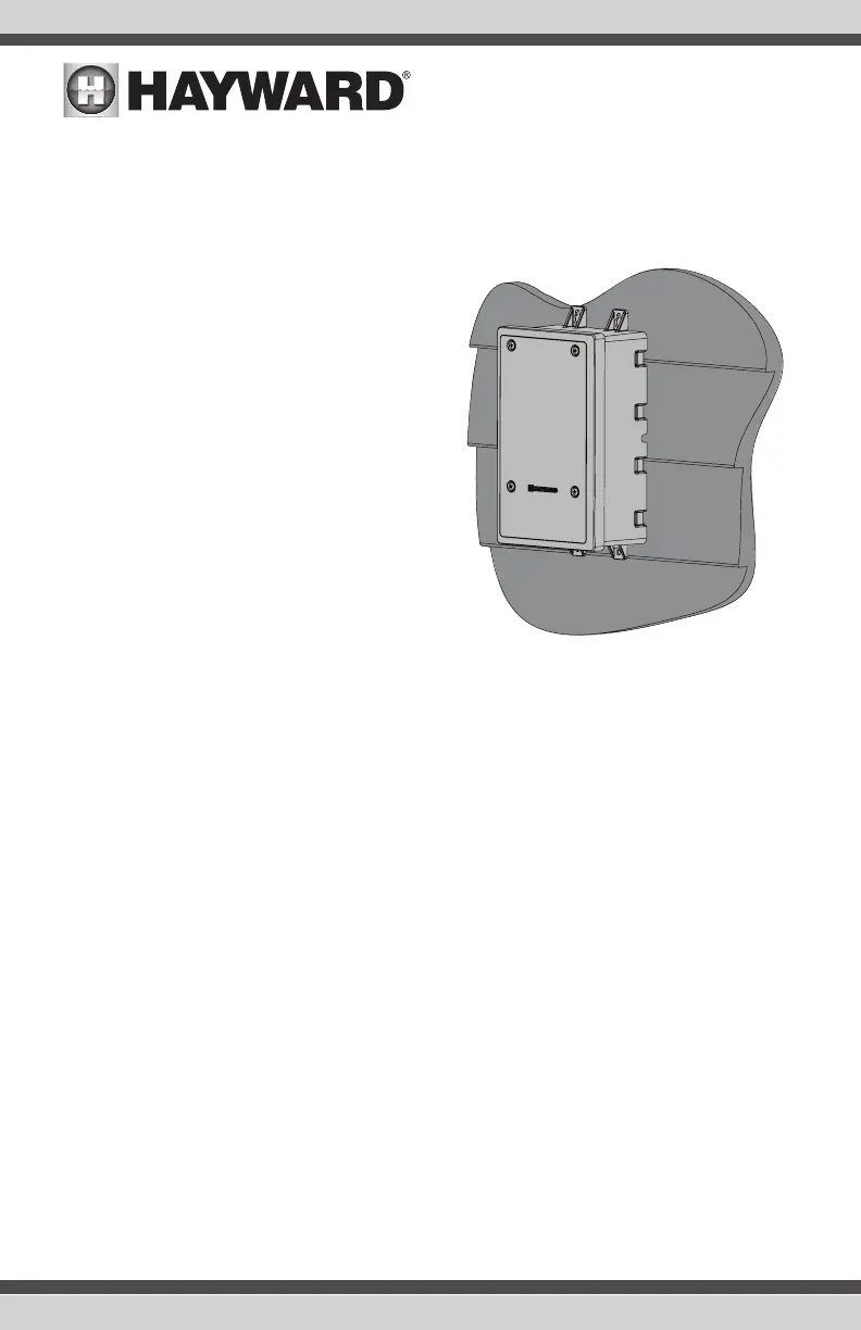
Mount the Hub on a wall or flat surface. Select
mounting hardware that is appropriate for the mounting surface and material. The Hub has two
keyhole type mounting tabs on the top and bottom of the enclosure requiring a total of 4 fasteners.
Control Pad
The Control Pad comes with a 15 ft cord and plugs into the Hub. It should be mounted in a location
that is convenient for the user to view and change pool/spa settings. When considering the mount-
ing location, make sure there is enough clearance above the enclosure so that the flip door will be
able to be opened fully. Also be sure to allow enough clearance below the Control Pad to access
the USB and Ethernet connectors. For best viewing results, position the Control Pad where it won't
be subjected to direct sunlight.
The Control Pad has two keyhole cutouts on the back of its enclosure. To mount, screw the two
provided fasteners into the mounting surface at the desired location as shown in the diagram on
page 8. Tighten until the bottom of the screw heads are 1/8" off the mounting surface. Position the
Control Pad cutouts over the screw and slide the unit downward. You may have to tighten or loosen
the screws slightly to fully engage the screw heads to get a snug fit.
7
USE ONLY HAYWARD GENUINE REPLACEMENT PARTS
 Loading...