
D
dakota98Aug 8, 2025
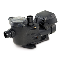
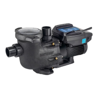
What to do if Hayward THP VS W3SP3206VSP has low flow?
- JjudithmullenAug 9, 2025
If your Hayward Power Pump has low flow: * Correct the piping size. * If you have sand, D.E. or Cartridge filters - backwash as per manufacturer’s instructions or clean/replace the cartridge. * Re-tighten the suction and discharge connections using PTFE tape if there is an air leak in suction (bubbles issuing from return fittings). Inspect other plumbing connections, and tighten as required. * If the impeller is plugged, restricted, or damaged, replace the impeller including a new seal assembly.